ELECTRONIC SHIFT LEVER SYSTEM, Diagnostic DTC:C2300
| DTC Code | DTC Name |
|---|---|
| C2300 | Actuator System Malfunction |
DESCRIPTION
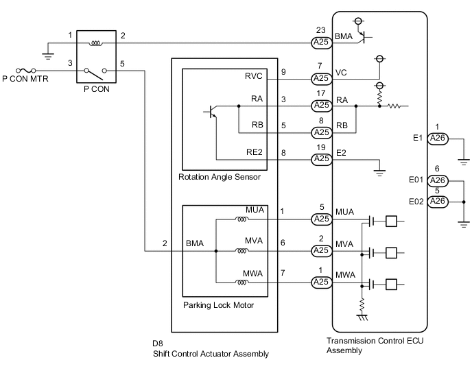
The shift control actuator assembly consists of the parking lock motor and the rotation angle sensor. The transmission control ECU assembly receives a P position switch signal from the EV control ECU and activates the parking lock motor by controlling current, causing the parking lock mechanism to switch. The transmission control ECU assembly also detects the rotor rotation angle through the rotation angle sensor to control timing of current application to the coils. The transmission control ECU assembly stores this DTC when it detects a malfunction in the shift control actuator system.
| DTC No. | Detection Item | DTC Detection Condition | Trouble Area | Warning Indicate | Memory |
|---|---|---|---|---|---|
| C2300 | Actuator System Malfunction | Decrease in the power source voltage (+B), open or short in the P CON relay (transaxle parking lock control relay) or shift control actuator assembly (parking lock motor or rotation angle sensor), or internal malfunction of the shift control actuator assembly (parking lock motor or rotation angle sensor). |
|
|
DTC stored |
WIRING DIAGRAM
CAUTION / NOTICE / HINT
Note
-
Do not remove/install the auxiliary battery or disconnect the cable from the negative (-) auxiliary battery terminal before instructed.
-
It may not be possible to clear the following DTCs using the GTS: DTC C2300 (Actuator System Malfunction), C2301 (Shift Changing Time Malfunction), C2303 (Short in Power Source Relay Circuit), C2304 (Open or Short Circuit in U Phase), C2305 (Open or Short Circuit in V Phase), C2306 (Open or Short Circuit in W Phase), C2307 (Power Supply) and C2309 (Open in B+ Circuit). In such cases, disconnect the P CON-MAIN fuse and wait for at least 60 seconds to clear the DTCs after the repair.
-
After turning the power switch off, waiting time may be required before disconnecting the cable from the negative (-) auxiliary battery terminal. Therefore, make sure to read the disconnecting the cable from the negative (-) auxiliary battery terminal notices before proceeding with work.
PROCEDURE
-
CHECK FREEZE FRAME DATA
-
Connect the GTS to the DLC3.
-
Turn the power switch on (IG).
-
Enter the following menus: Body Electrical / Transmission Control / Trouble Codes.
-
Read the freeze frame data "Current flag record" of C2300.
Body Electrical > Transmission Control > Trouble Codes
Body Electrical > Transmission ControlTester Display Current flag record Result Result Proceed to OFF A ON B -
Turn the power switch off.
B 
REPLACE TRANSMISSION CONTROL ECU ASSEMBLY Click here
A 
-
-
CHECK DTC OUTPUT (TRANSMISSION CONTROL)
-
Connect the GTS to the DLC3.
-
Turn the power switch on (IG).
-
Enter the following menus: Body Electrical / Transmission Control / Trouble Codes.
-
Check if DTCs are output.
Body Electrical > Transmission Control > Trouble CodesResult Result Proceed to The following DTCs are not output. A Any of the following DTCs are output. B DTC No. Relevant Diagnosis C2304 Open or Short Circuit in U Phase C2305 Open or Short Circuit in V Phase C2306 Open or Short Circuit in W Phase -
Turn the power switch off.
B
GO TO DTC CHART (ELECTRONIC SHIFT LEVER SYSTEM) Click here
A
-
-
CHECK FREEZE FRAME DATA
-
Connect the GTS to the DLC3.
-
Turn the power switch on (IG).
-
Enter the following menus: Body Electrical / Transmission Control / Trouble Codes.
-
Read the freeze frame data of C2300.
Body Electrical > Transmission Control > Trouble Codes
Body Electrical > Transmission ControlTester Display IG(+B) Voltage Value Result Result Proceed to IG (+B) voltage is 9 V or higher A IG (+B) voltage is less than 9 V B -
Turn the power switch off.
B 
CLEAR DTC Click here
A
-
-
CLEAR DTC
-
Connect the GTS to the DLC3.
-
Turn the power switch on (IG).
-
Enter the following menus: Body Electrical / Transmission Control / Trouble Codes.
-
Read and record the DTCs and freeze frame data.
Body Electrical > Transmission Control > Trouble Codes -
Turn the power switch off.
-
Disconnect the P CON-MAIN fuse and wait for at least 60 seconds.
-
Check for DTCs again to see if the DTCs are cleared.
Body Electrical > Transmission Control > Clear DTCsResult Proceed to NEXT
NEXT
GO TO STEP 7 Click here
-
-
CLEAR DTC
-
Connect the GTS to the DLC3.
-
Turn the power switch on (IG).
-
Enter the following menus: Body Electrical / Transmission Control / Trouble Codes.
-
Read and record the DTCs and freeze frame data.
Body Electrical > Transmission Control > Trouble Codes -
Turn the power switch off.
-
Disconnect the P CON-MAIN fuse and wait for at least 60 seconds.
-
Check for DTCs again to see if the DTCs are cleared.
Body Electrical > Transmission Control > Clear DTCsResult Proceed to NEXT
NEXT
-
-
INSPECT AUXILIARY BATTERY
-
Inspect the auxiliary battery.
Result Result Proceed to Auxiliary battery is OK A Recharge auxiliary battery Replace auxiliary battery B
B
REPLACE AUXILIARY BATTERY Click here
A
-
-
CHARGE AUXILIARY BATTERY
-
Charge the auxiliary battery.
Result Proceed to NEXT
NEXT
GO TO STEP 9 Click here
-
-
REPLACE AUXILIARY BATTERY
-
Replace the auxiliary battery.
Result Proceed to NEXT
NEXT
-
-
CHECK DTC OUTPUT (SIMULATION TEST)
-
Connect the GTS to the DLC3.
-
Release the brake pedal and turn the power switch on (IG).
Tech Tips
Do not turn the power switch on (READY).
-
Depress the brake pedal and move the shift lever to select neutral (N).
-
Enter the following menus: Body Electrical / Transmission Control / Trouble Codes.
-
Check if DTCs are output.
Body Electrical > Transmission Control > Trouble CodesResult Result Proceed to DTC C2300 is output. A DTC C2300 is not output. B -
Turn the power switch off.
B
END (AUXILIARY BATTERY WAS INSUFFICIENTLY CHARGED)
A
-
-
CHECK HARNESS AND CONNECTOR (TRANSMISSION CONTROL ECU ASSEMBLY - SHIFT CONTROL ACTUATOR ASSEMBLY)
-
Disconnect the transmission control ECU assembly connector.
-
Disconnect the shift control actuator assembly connector.
-
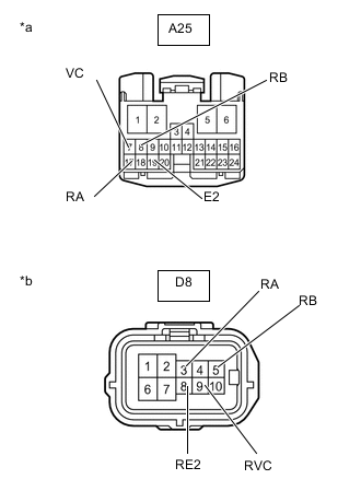
*a Front view of wire harness connector
(to Transmission Control ECU Assembly)
*b Front view of wire harness connector
(to Shift Control Actuator Assembly)
Measure the resistance according to the value(s) in the table below.
Standard Resistance Tester Connection Switch Condition Specified Condition A25-7 (VC) - D8-9 (RVC) Power switch off Below 1 Ω A25-17 (RA) - D8-3 (RA) Power switch off Below 1 Ω A25-8 (RB) - D8-5 (RB) Power switch off Below 1 Ω A25-19 (E2) - D8-8 (RE2) Power switch off Below 1 Ω A25-7 (VC) or D8-9 (RVC) - Body ground and other terminals Power switch off 10 kΩ or higher A25-17 (RA) or D8-3 (RA) - Body ground and other terminals Power switch off 10 kΩ or higher A25-8 (RB) or D8-5 (RB)- Body ground and other terminals Power switch off 10 kΩ or higher A25-19 (E2) or D8-8 (RE2) - Body ground and other terminals Power switch off 10 kΩ or higher -
Reconnect the shift control actuator assembly connector.
-
Reconnect the transmission control ECU assembly connector.
Result Proceed to OK NG
NG
REPAIR OR REPLACE HARNESS OR CONNECTOR
OK
-
-
CHECK SHIFT CONTROL ACTUATOR ASSEMBLY (ROTATION ANGLE SENSOR)
-
Disconnect the transmission control ECU assembly connector.
-
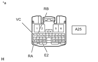
*a Front view of wire harness connector
(to Transmission Control ECU Assembly)
Measure the resistance according to the value(s) in the table below.
Standard Resistance Tester Connection Switch Condition Specified Condition A25-7 (VC) - A25-17 (RA) Power switch off 10 kΩ or higher A25-7 (VC) - A25-8 (RB) Power switch off 10 kΩ or higher A25-7 (VC) - A25-19 (E2) Power switch off 520 to 600 Ω A25-17 (RA) - A25-8 (RB) Power switch off 10 kΩ or higher A25-17 (RA) - A25-19 (E2) Power switch off 10 kΩ or higher A25-8 (RB) - A25-19 (E2) Power switch off 10 kΩ or higher -
Reconnect the transmission control ECU assembly connector.
Result Proceed to OK NG
NG
REPLACE SHIFT CONTROL ACTUATOR ASSEMBLY Click here
OK
-
-
CHECK HARNESS AND CONNECTOR (TRANSMISSION CONTROL ECU ASSEMBLY - BODY GROUND)
-
Disconnect the transmission control ECU assembly connector.
-
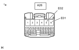
*a Front view of wire harness connector
(to Transmission Control ECU Assembly)
Measure the resistance according to the value(s) in the table below.
Standard Resistance Tester Connection Switch Condition Specified Condition A26-6 (E01) - Body ground Power switch off Below 1 Ω A26-5 (E02) - Body ground Power switch off Below 1 Ω -
Reconnect the transmission control ECU assembly connector.
Result Proceed to OK NG
NG
REPAIR OR REPLACE HARNESS OR CONNECTOR
OK
-
-
CHECK SHIFT CONTROL ACTUATOR ASSEMBLY
-
Apply that the parking brake.
-
Disconnect the D8 shift control actuator assembly connector.
-
Remove the 3 shift control actuator bolts.
-
Slightly pull the shift control actuator assembly away from the FCV transaxle with motor assembly.
-
Reconnect the D8 shift control actuator assembly connector.
-
Make sure the brake pedal is not depressed and turn the power switch on (ACC).
Note
The shift control actuator assembly may operate if the power switch is turned on (IG) or on (READY). Do not turn the power switch on (IG) or on (READY) during this inspection to prevent the shift control actuator assembly from operating while in contact with the splines.
-
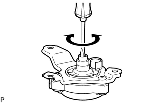
Using a screwdriver with its tip wrapped with protective tape or a piece of cloth, rotate the shaft.
Note
-
Make sure to use a screwdriver with its tip wrapped with protective tape or a piece of cloth to prevent the splines of the actuator from being damaged.
-
The shift control actuator assembly cannot be disassembled.
-
Confirm that the shaft of the shift control actuator assembly rotates smoothly.
OK The shaft of the shift control actuator assembly rotates smoothly. -
Measure the voltage according to the value(s) in the table below.
Tech Tips
If the shaft is rotated quickly, the voltage value may not become a pulse waveform, so rotate the shaft at a speed of 1 rotation every 6 seconds.
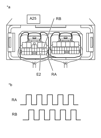
*a Component with harness connected
(Transmission Control ECU Assembly)
*b Output Waveform while Shaft of Shift Control Actuator Assembly being Rotated (Example) Standard Voltage Tester Connection Condition Specified Condition A25-17 (RA) - A25-19 (E2) Power switch on (ACC), shaft being rotated 0 to 1.5 V ←→ 4 to 5.5 V A25-8 (RB) - A25-19 (E2) Power switch on (ACC), shaft being rotated 0 to 1.5 V ←→ 4 to 5.5 V
-
-
Turn the power switch off.
Result Proceed to OK NG
NG
REPLACE SHIFT CONTROL ACTUATOR ASSEMBLY Click here
OK
-
-
CHECK FCV TRANSAXLE WITH MOTOR ASSEMBLY
-
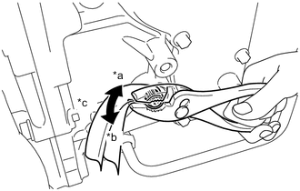
*a Lock *b Unlock *c Rotate approximately 20° Wrap the shaft with a piece of cloth and turn it using pliers.
OK The shaft rotates smoothly in the lock and unlock directions. Note
During this inspection, make sure to use a piece of cloth to prevent the shaft splines from being damaged.
Tech Tips
Rotate the shaft using torque between 4.0 to 7.0 N*m (41 to 71 kgf*cm, 36 to 61 in.*lbf).
-
Set the shaft in the lock position after the inspection.
Result Proceed to OK NG
OK
REPLACE TRANSMISSION CONTROL ECU ASSEMBLY Click here
NG
REPLACE FCV TRANSAXLE WITH MOTOR ASSEMBLY Click here
-