ELECTRONIC SHIFT LEVER SYSTEM, Diagnostic DTC:C2309
| DTC Code | DTC Name |
|---|---|
| C2309 | Open in B+ Circuit |
DESCRIPTION
Auxiliary battery voltage will be applied to the +B terminal when the power switch is turned on (IG). When a +B terminal voltage malfunction is detected, the transmission control ECU assembly stores this DTC.
| DTC No. | Detection Item | DTC Detection Condition | Trouble Area | Warning Indicate | Memory |
|---|---|---|---|---|---|
| C2309 | Open in B+ Circuit | With the power switch on (IG), voltage of transmission control ECU assembly terminal +B is 3 V or less for 1 second or more. |
|
|
DTC stored |
CAUTION / NOTICE / HINT
Note
-
Do not remove/install the auxiliary battery or disconnect the cable from the negative (-) auxiliary battery terminal before instructed.
-
It may not be possible to clear the following DTCs using the GTS: DTC C2300 (Actuator System Malfunction), C2301 (Shift Changing Time Malfunction), C2303 (Short in Power Source Relay Circuit), C2304 (Open or Short Circuit in U Phase), C2305 (Open or Short Circuit in V Phase), C2306 (Open or Short Circuit in W Phase), C2307 (Power Supply) and C2309 (Open in B+ Circuit). In such cases, disconnect the P CON-MAIN fuse and wait for at least 60 seconds to clear the DTCs after the repair.
-
After turning the power switch off, waiting time may be required before disconnecting the cable from the negative (-) auxiliary battery terminal. Therefore, make sure to read the disconnecting the cable from the negative (-) auxiliary battery terminal notices before proceeding with work.
PROCEDURE
-
READ VALUE USING GTS (IG(+B) VOLTAGE VALUE)
-
Connect the GTS to the DLC3.
-
Turn the power switch on (IG).
-
Enter the following menus: Body Electrical / Transmission Control / Data List / IG(+B) Voltage Value.
-
Read the Data List displayed on the GTS.
Body Electrical > Transmission Control > Data ListTester Display IG(+B) Voltage Value Result Result Proceed to 3 V or less A Other than above B -
Turn the power switch off.
B 
REPLACE TRANSMISSION CONTROL ECU ASSEMBLY Click here
A 
-
-
INSPECT FUSE
-
Remove the IGCT NO. 1 fuse and FDC fuse from the motor compartment relay block.
-
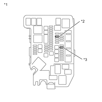
*1 Motor Compartment Relay Block *2 IGCT NO. 1 fuse *3 FDC fuse Measure the resistance according to the value(s) in the table below.
Standard Resistance Tester Connection Condition Specified Condition IGCT NO. 1 fuse Always Below 1 Ω FDC fuse Always Below 1 Ω -
Install the IGCT NO. 1 fuse and FDC fuse.
Result Proceed to OK NG
NG
REPLACE FUSE (IGCT NO. 1, FDC)
OK
-
-
READ VALUE USING GTS (BATTERY VOLTAGE VALUE)
-
Connect the GTS to the DLC3.
-
Turn the power switch on (IG).
-
Enter the following menus: Body Electrical / Transmission Control / Data List / Battery Voltage Value.
-
Read the Data List displayed on the GTS.
Body Electrical > Transmission Control > Data ListTester Display Battery Voltage Value Result Result Proceed to 9 V or higher A Less than 9 V B -
Turn the power switch off.
B
CHARGE OR REPLACE AUXILIARY BATTERY Click here
A
-
-
CHECK HARNESS AND CONNECTOR (TRANSMISSION CONTROL ECU ASSEMBLY - FDC FUSE)
-
Disconnect the transmission control ECU assembly connector.
-
Remove the FDC fuse from the motor compartment relay block.
-
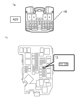
*1 Motor Compartment Relay Block *2 FDC Fuse Holder *a Front view of wire harness connector
(to Transmission Control ECU Assembly)
Measure the resistance according to the value(s) in the table below.
Standard Resistance Tester Connection Switch Condition Specified Condition A25-16 (+B) - 2 (FDC fuse holder) Power switch off Below 1 Ω A25-16 (+B) or 2 (FDC fuse holder) - Body ground and other terminals Power switch off 10 kΩ or higher Note
Be careful not to break the fuse holder by forcing the tester probes into it during this inspection.
-
Install the FDC fuse.
-
Reconnect the transmission control ECU assembly connector.
Result Proceed to OK NG
OK
CHECK AND REPAIR POWER SOURCE CIRCUIT
NG
REPAIR OR REPLACE HARNESS OR CONNECTOR
-