TUBE JOINT(for Inlet Side) REMOVAL
CAUTION / NOTICE / HINT
The necessary procedures (adjustment, calibration, initialization, or registration) that must be performed after parts are removed, installed, or replaced during the tube joint (for Inlet Side) removal/installation are shown below.
| Replacement Part or Procedure | Necessary Procedure | Effects/Inoperative when not Performed | Link |
|---|---|---|---|
| Remove/install height control sensor RR |
|
Automatic headlight beam level control system | |
| Remove/install rear axle beam |
|
VSC malfunctioning | |
| Adjust lane departure warning camera | Lane departure alert system does not operate correctly. |
Note
When removing or installing the rear disc brake caliper assembly, if the piston of the brake caliper is pushed in, the clearance between the brake pad and rear disc will become large. In this condition, depressing the brake pedal may cause DTC C1214 (Hydraulic Control System Malfunction) to be stored, so check and clear DTCs after the procedure is complete.
CAUTION:
-
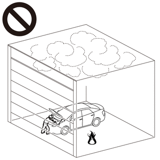
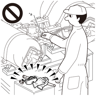
Work procedures must be performed in an area with good ventilation (airflow) where hydrogen gas will not accumulate, and flames or other things that could act as ignition sources must not be present.
-
Accumulated hydrogen gas could ignite, resulting in a serious accident.
-
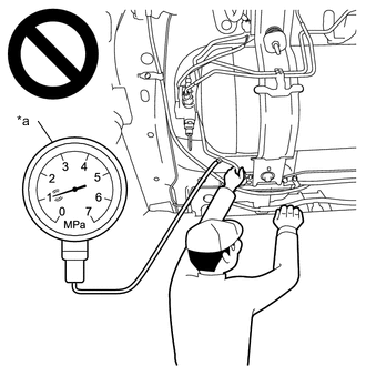
*a When inside of piping is pressurized Do not install or remove any hydrogen system components without first performing depressurization procedures.
-
The highly pressurized hydrogen gas inside the hydrogen tank assembly could blow out, resulting in a serious accident.
-
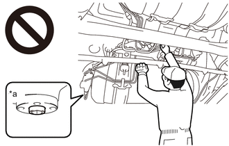
*a Manual Valve Open Do not perform depressurization procedures when the manual valve of the hydrogen tank assembly is open.
-
The highly pressurized hydrogen gas inside the hydrogen tank assembly could blow out, resulting in a serious accident.
-
When performing depressurization, do not perform procedures by hand without wearing protective glasses and gloves.
-
The highly pressurized hydrogen gas inside the hydrogen tank assembly could blow out, resulting in a serious accident.
-
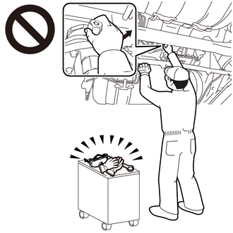
*a After depressurization procedures, the high pressure piping union nut that is loosened first. After performing depressurization procedures, when first loosening the union nut of the high pressure hydrogen piping, do not loosen the union nut by hand without wearing protective glasses and gloves.
-
Even when depressurization procedures are performed, the pressurized hydrogen gas inside the high pressure hydrogen piping cannot be completely depressurized, so the highly pressurized hydrogen gas remaining in the high pressure hydrogen piping could blow out, resulting in a serious accident.
-
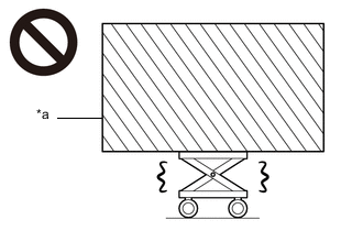
*a Heavy load exceeding the weight limits or size limits of the engine lifter Because the hydrogen tank unit is extremely heavy, make sure to follow the work procedures described in the repair manual.
-
If work is not performed according to the procedures described in the repair manual, there is a danger that the engine lifter could drop and components could fall down.
PROCEDURE
-
PRECAUTION
Note
-
After turning the power switch off, waiting time may be required before disconnecting the cable from the negative (-) auxiliary battery terminal. Therefore, make sure to read the disconnecting the cable from the negative (-) auxiliary battery terminal notices before proceeding with work.
-
Place signs [HIGH PRESSURE GAS WORK IN PROGRESS - DO NOT TOUCH!], etc. to warn other technicians to be cautious. (An example sign is included, so make a copy and use it.)
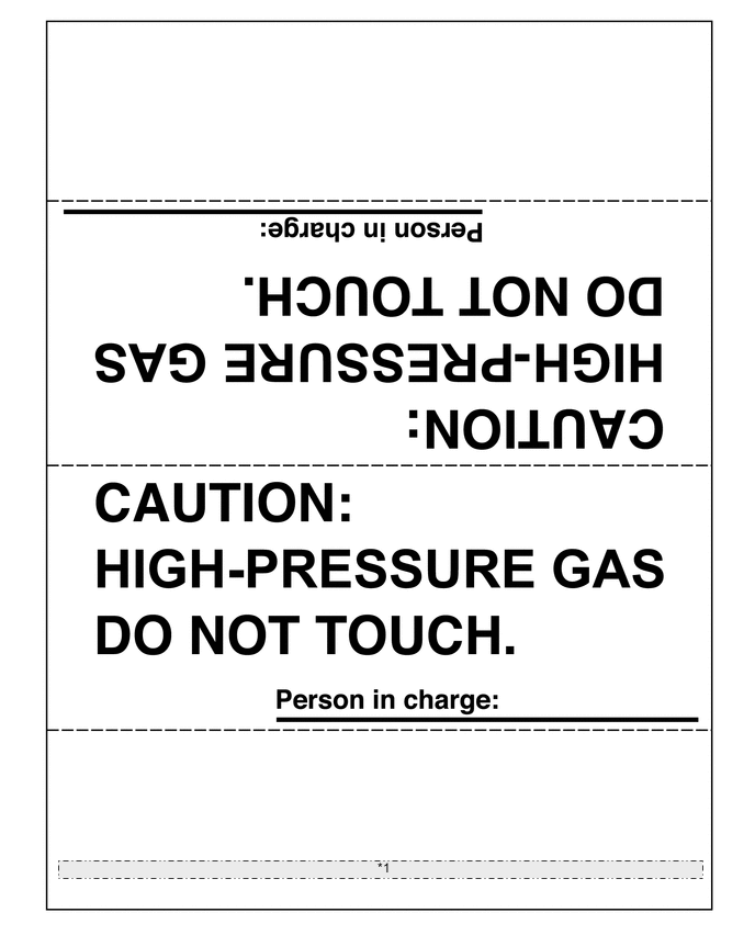
*1 Place signs [HIGH PRESSURE GAS WORK IN PROGRESS - DO NOT TOUCH!], etc. to warn other technicians to be cautious. (An example sign is included, so make a copy and use it.) -
When performing depressurization, do not open or close any parts of the hydrogen gas piping except for the following:
- Adjustment bolt of the hydrogen tank assembly manual valve
- Tank shut valve of the hydrogen tank assembly
- No. 1 hydrogen supply regulator plug
-
When installing or removing hydrogen system components (hydrogen tank assembly, high pressure hydrogen piping, hydrogen inlet receptacle, hydrogen tube joint, hydrogen tank pressure sensor or hydrogen supply regulator assembly), to prevent strain such as twisting from being applied to the high pressure hydrogen piping, use the hydrogen tank installation and removal guide tool and remove the hydrogen tank unit from the vehicle before performing procedures.
-
Even when replacing only the No. 1 hydrogen tank assembly, or only the No. 2 hydrogen tank assembly, to prevent strain from being applied to the high pressure hydrogen piping, use the tank positioning attachment of the hydrogen tank installation and removal tool, and perform positioning of the No. 1 hydrogen tank assembly and No. 2 hydrogen tank assembly.
-
Even when not removing or installing the high pressure hydrogen piping, be careful not to pull or otherwise apply strain to the high pressure hydrogen piping.
-
Do not reuse high pressure hydrogen piping after it has been removed, because the coupling portions will not maintain their airtightness.
-
When reusable parts such as the hydrogen tank assembly valve portion, hydrogen inlet receptacle, hydrogen tube joint and hydrogen supply regulator assembly have been removed, to protect the seal portions and threaded portions from damage as well as to prevent foreign matter such as dust and metal fragments from entering through openings, cover these areas with protective tape.
-
Do not use packing tape, or any other tape that will leave residue on parts, as protective tape.
-
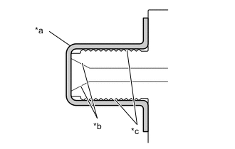
*a Protective Tape *b Seal Portion *c Threaded Portion Protect seal portions and threaded portions as shown in the illustration.
-
To protect the seal portions and threaded portions from damage or contamination by foreign matter, remove the protective tape immediately before installation.
-
When reassembling components that have been removed, make sure that there is no foreign matter adhering to the openings.
-
After installing hydrogen system components, first perform primary leak inspection with low pressure nitrogen gas, and then fill pressurized hydrogen gas at a hydrogen station to perform secondary leak inspection. When performing secondary leak inspection, the vehicle cannot be driven to the hydrogen station under its own power, so transport it using a car carrier, etc.
-
When the vehicle is parked with the power switch off, if the FC control ECU judges that the FC stack temperature will go below 0°C (32°F), it activates the FC air compressor, hydrogen pump and FC cooling water pump for a maximum of 180 seconds and drains water from the FC stack assembly. When performing inspection or repairs with the power switch off (not on (IG) or on (READY)), disconnect the cable from the negative (-) auxiliary battery terminal before performing work.
-
-
REMOVE HYDROGEN TANK UNIT
-
REMOVE NO. 2 HYDROGEN SUPPLY TUBE SUB-ASSEMBLY
-
REMOVE WIRE HARNESS CLAMP
-
Disengage the clamp and separate the No. 2 hydrogen tank assembly connector from the hydrogen tank tube clamp bracket.
-
Disengage the clamp and remove the wire harness clamp from the hydrogen tank tube sub-assembly and wire harness of the No. 2 hydrogen tank assembly.
-
-
REMOVE HYDROGEN TANK TUBE CLAMP BRACKET
-
REMOVE NO. 1 FUEL TUBE CLAMP
-
REMOVE FUEL TUBE GROMMET
-
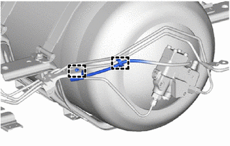
REMOVE HYDROGEN TANK TUBE ASSEMBLY
-
REMOVE NO. 3 HYDROGEN TANK TUBE
-
REMOVE NO. 2 HYDROGEN TANK TUBE
-
REMOVE FUEL TUBE GROMMET
-
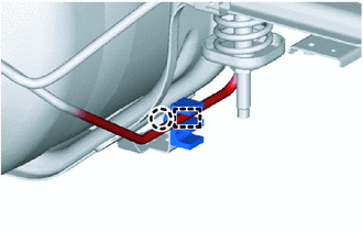
Disengage the clamp and separate the No. 4 hydrogen tank tube from the fuel tube grommet.
Note
-
Do not damage or deform the No. 4 hydrogen tank tube.
-
If the pipe protector material of the No. 4 hydrogen tank tube is damaged so that the internal pipe itself becomes visible, replace the No. 4 hydrogen tank tube with a new one.
-
If the hydrogen tank tube was separated from the fuel tube grommet, replace the fuel tube grommet with a new one.
-
If it is difficult to separate the No. 4 hydrogen tank tube, cut off the claw of the fuel tube grommet and separate the No. 4 hydrogen tank tube.
-
-
Disengage the claw and remove the fuel tube grommet from the front hydrogen tank frame sub-assembly LH.
Note
Do not reuse the fuel tube grommet.
-
-
REMOVE HYDROGEN TANK TUBE JOINT
-
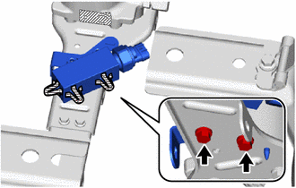
Remove the 2 bolts and hydrogen tank tube joint from the front center hydrogen tank frame.
Note
If the hydrogen tank tube joint has been dropped or subjected to a strong impact, replace the hydrogen tank tube joint and hydrogen tank pressure sensor with a new one.
-
-
REMOVE HYDROGEN TANK TUBE JOINT INLET BRACKET
-
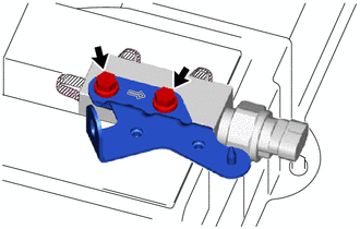
Secure the hydrogen tank tube joint in a vise between aluminum plates.
Note
-
Be careful not to scratch or damage the seal portions or threaded portions.
-
Do not overtighten the vise.
-
If the hydrogen tank tube joint has been dropped or subjected to a strong impact, replace the hydrogen tank tube joint and hydrogen tank pressure sensor with a new one.
-
-
Remove the 2 bolts and hydrogen tank tube joint inlet bracket from the hydrogen tank tube joint.
Note
If the hydrogen tank tube joint has been dropped or subjected to a strong impact, replace the hydrogen tank tube joint and hydrogen tank pressure sensor with a new one.
-