HYDROGEN TANK ASSEMBLY INSTALLATION

PROCEDURE
-
REPLACE LABEL
Tech Tips
This procedure is for when the No. 1 hydrogen tank assembly or No. 2 hydrogen tank assembly is replaced, and the contents of the labels applied to the fuel filler opening lid assembly and hood assembly are changed.
-
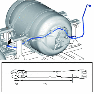
Peel off the label cover film applied over the hydrogen tank pressure information label.
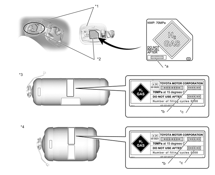
*1 Fuel Filler Opening Lid Assembly *2 Hydrogen Tank Pressure Information Label *3 No. 1 Hydrogen Tank Assembly *4 No. 2 Hydrogen Tank Assembly *a Tape with DO NOT USE AFTER date recorded *b Location to record Tank Inspection Passed date *c Location to record DO NOT USE AFTER date - - Note
When peeling off the label cover film, if the hydrogen tank pressure information label is also peeled off, replace it with a new hydrogen tank pressure information label.
-
Record the item onto new tape.
Recorded Item Recorded Contents DO NOT USE AFTER date From the 2 hydrogen tank assemblies installed to the vehicle, use the Tank Inspection Passed date of whichever tank has an older date, and starting from a point 1 month before the Tank Inspection Passed date, record a month/year that is 20 years in the future.
Example:
If the Tank Inspection Passed dates of each hydrogen tank assembly are as follows:
No. 1 Hydrogen Tank Assembly: 2014.3, No. 2 Hydrogen Tank Assembly: 2014.4
The No. 1 Hydrogen Tank Assembly has an older date, so record the date as 2034.2
Note
-
Use the largest text size that can fit in the label width, and space it as compactly as possible.
-
When writing the text by hand, be sure to write the letters and numbers clearly and distinctly so that there can be no confusion.
Tech Tips
When recording the items with the label printer, use black lettering on transparent tape.
Label font, cartridge size and tape width Font Cartridge (mm (in.)) Tape Width (mm (in.)) Gothic 4.0 (0.1575) 20 (0.7874) -
-
Apply the tape with item recorded to the hydrogen tank pressure information label.
-
Apply new label cover film over the hydrogen tank pressure information label.
Note
When applying the tape, avoid air bubbles as much as possible.
-
-
INSTALL FRONT HYDROGEN TANK FRAME SPRING BOLT CUSHION
Tech Tips
This procedure is only performed when the front hydrogen tank frame spring bolt cushion is being replaced with a new one.
-
Engage the 2 claws and install the front hydrogen tank frame spring bolt cushion to the front hydrogen tank frame sub-assembly LH and front hydrogen tank frame sub-assembly RH.
Tech Tips
Use the same procedure to install the other front hydrogen tank frame spring bolt cushions.
-
-
INSTALL REAR HYDROGEN TANK FRAME SPRING BOLT CUSHION
Tech Tips
This procedure is only performed when the rear hydrogen tank frame spring bolt cushion is being replaced with a new one.
-
Engage the 2 clamps and install the rear hydrogen tank frame spring bolt cushion to the rear hydrogen tank frame sub-assembly.
Tech Tips
Use the same procedure to install the other rear hydrogen tank frame spring bolt cushions.
-
-
INSTALL FRONT HYDROGEN TANK FRAME SEAT
Tech Tips
This procedure is only performed when the front hydrogen tank frame seat is being replaced with a new one.
-
Install the front hydrogen tank frame seat to the front hydrogen tank frame sub-assembly and front hydrogen tank frame sub-assembly RH.
Note
Make sure the rear hydrogen tank frame seat is not damaged.
Tech Tips
Use the same procedure to install the other front hydrogen tank frame seats.
-
-
INSTALL REAR HYDROGEN TANK FRAME SEAT
Tech Tips
This procedure is only performed when the rear hydrogen tank frame seat is being replaced with a new one.
-
Install the rear hydrogen tank frame seat to the rear hydrogen tank frame sub-assembly.
Note
Make sure the rear hydrogen tank frame seat is not damaged.
Tech Tips
Use the same procedure to install the other rear hydrogen tank frame seats.
-
-
INSTALL FRONT HYDROGEN TANK FRAME SUB-ASSEMBLY RH
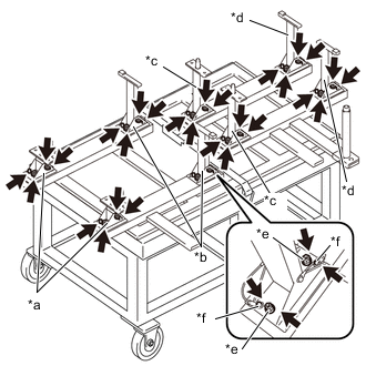
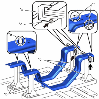
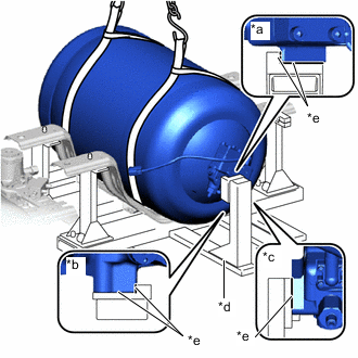
*a SST (Support No. 1) *b SST (Support No. 2) *c SST (Support No. 3) *d SST (Support No. 4) *e SST (Bolt) *f Pin Tech Tips
To avoid applying strain to the high pressure hydrogen piping, use the SST (hydrogen tank stand) to position the No. 1 hydrogen tank assembly and No. 2 hydrogen tank assembly.
-
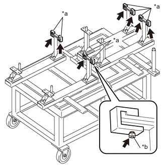
Loosen the SST (bolts) of each tank support type SST of the SST (hydrogen tank stand).
- SST
- 09403-62010 ( 09403-06010, 09403-06020, 09403-06030, 09403-06040, 09403-06080 )
-
Insert the 2 pins of each tank support type SST of the SST (hydrogen tank stand) into the pin holes of the SST (hydrogen tank stand) main body, and tighten the SST (bolts).
-
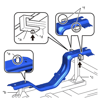
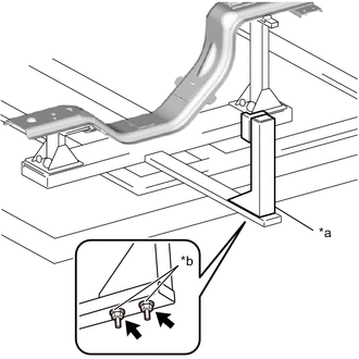
*a SST (Tank Belt Fixture) *b SST (Support No. 1) *c SST (Support No. 2) *d SST (Bolt) *e Pin *f Groove Set the front hydrogen tank frame sub-assembly RH to each tank support type SST.
- SST
- 09403-62010 ( 09403-06010, 09403-06020, 09403-06080 )
Note
-
Insert the pin of the SST (support No. 1) into the pin hole of the front hydrogen tank frame sub-assembly RH.
-
Align the edge of the front hydrogen tank frame sub-assembly RH with the groove of the SST (support No. 2).
-
Using the SST (bolts), install each SST (tank belt fixture) and support the front hydrogen tank frame sub-assembly RH.
- SST
- 09403-62010 ( 09403-06100, 09403-06110 )
-
-
INSTALL FRONT HYDROGEN TANK FRAME SUB-ASSEMBLY LH
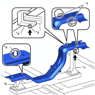
*a SST (Tank Belt Fixture) *b SST (Support No. 1) *c SST (Support No. 2) *d SST (Bolt) *e Pin *f Groove Tech Tips
To avoid applying strain to the high pressure hydrogen piping, use the SST (hydrogen tank stand) to position the No. 1 hydrogen tank assembly and No. 2 hydrogen tank assembly.
-
Set the front hydrogen tank frame sub-assembly LH to each tank support type SST.
- SST
- 09403-62010 ( 09403-06010, 09403-06020, 09403-06080 )
Note
-
Insert the pin of the SST (support No. 1) into the pin hole of the front hydrogen tank frame sub-assembly LH.
-
Align the edge of the front hydrogen tank frame sub-assembly LH with the groove of the SST (support No. 2).
-
Using the SST (bolts), install each SST (tank belt fixture) and support the front hydrogen tank frame sub-assembly LH.
- SST
- 09403-62010 ( 09403-06100, 09403-06110 )
-
-
INSTALL REAR HYDROGEN TANK FRAME SUB-ASSEMBLY
*a SST (Tank Belt Fixture) *b SST (Support No. 3) *c SST (Support No. 4) *d SST (Bolt) *e Pin *f Groove Tech Tips
To avoid applying strain to the high pressure hydrogen piping, use the SST (hydrogen tank stand) to position the No. 1 hydrogen tank assembly and No. 2 hydrogen tank assembly.
-
Set the 2 rear hydrogen tank frame sub-assemblies to each tank support type SST.
- SST
- 09403-62010 ( 09403-06030, 09403-06040, 09403-06080 )
Note
-
Insert the pin of the SST (support No. 3) into the pin hole of the rear hydrogen tank frame sub-assembly.
-
Align the edge of the rear hydrogen tank frame sub-assembly with the groove of the SST (support No. 4).
-
Using the SST (bolts), install each SST (tank belt fixture) and support the 2 rear hydrogen tank frame sub-assemblies.
- SST
- 09403-62010 ( 09403-06100, 09403-06110 )
-
-
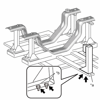
INSTALL FRONT CENTER HYDROGEN TANK FRAME
-
Temporarily install the front center hydrogen tank frame to the front hydrogen tank frame sub-assembly LH and front hydrogen tank frame sub-assembly RH with the 4 bolts.
-
Fully tighten the 4 bolts.
- Torque:
- 13 N*m { 133 kgf*cm, 10 ft.*lbf }
-
-
INSTALL NO. 1 HYDROGEN TANK ASSEMBLY
*a SST (Support No. 5) *b SST (Nut) Tech Tips
To avoid applying strain to the high pressure hydrogen piping, use the SST (hydrogen tank stand) to position the No. 1 hydrogen tank assembly and No. 2 hydrogen tank assembly.
-
Install the SST (support No. 5) with the SST (nuts).
- SST
- 09403-62010 ( 09403-06050, 09403-06090 )
-

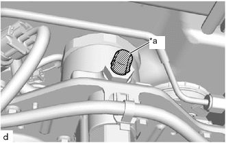
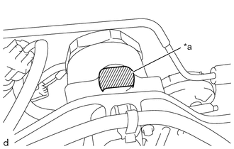
*a Valve Edge As shown in the illustration, adjust the position of the No. 1 hydrogen tank assembly so that its valve edge is in the vertical direction.
-
Using the engine sling device and belt, hoist up the No. 1 hydrogen tank assembly.
Note
Do not allow the No. 1 hydrogen tank assembly to fall.
-
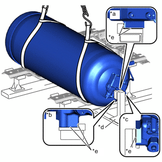
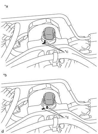
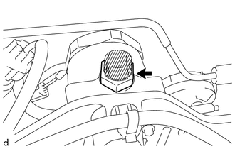
*a Upper View *b Lower View *c Side View *d SST (Support No. 5) *e Make sure there is no gap As shown in the illustration, slowly press the valve edge of the No. 1 hydrogen tank assembly against the SST (support No. 5), and set the No. 1 hydrogen tank assembly to the front hydrogen tank frame sub-assembly LH and front hydrogen tank frame sub-assembly RH.
- SST
- 09403-62010 ( 09403-06050 )
Note
-
To prevent the rubber sheet from being moved out of position, perform positioning with the No. 1 hydrogen tank assembly lifted up.
-
Make sure that there is no gap between the valve edge of the No. 1 hydrogen tank assembly and the SST (support No. 5).
-
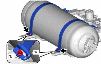
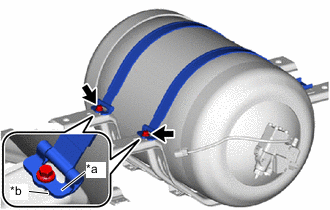
*a Hinge *b Detent Temporarily tighten the 2 front hydrogen tank band sub-assemblies to the front hydrogen tank frame sub-assembly LH and front hydrogen tank frame sub-assembly RH with the 2 bolts.
Note
Make sure the hinge does not ride up on the detent.
-
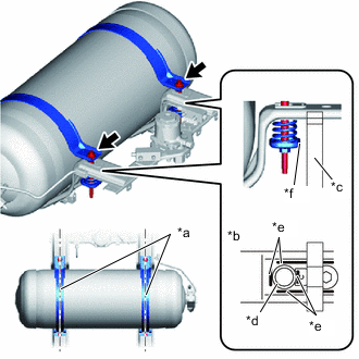
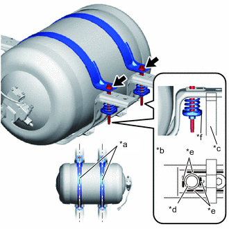
*a Parallel *b Lower View *c SST (Support No. 2) *d Compression Spring *e Bent Flange *f Edge Temporarily tighten the front hydrogen tank band sub-assembly with the 2 bolts, 2 front hydrogen tank spring bolt cups and 2 compression springs.
- SST
- 09403-62010 ( 09403-06020 )
Note
-
Set the front hydrogen tank band sub-assembly parallel with the front hydrogen tank frame sub-assembly LH and front hydrogen tank frame sub-assembly RH.
-
Make sure the compression spring does not ride up onto the bent flange of the front hydrogen tank frame sub-assembly LH or front hydrogen tank frame sub-assembly RH.
-
Install so that the edge of the front hydrogen tank spring bolt cup and the SST (support No. 2) are parallel.
-
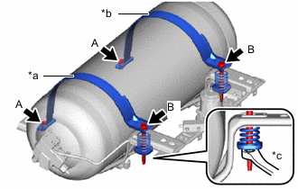
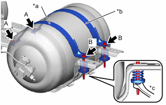
*a for LH Side *b for RH Side *c Hold Fully tighten the 2 bolts (A) (hinge side).
- Torque:
- 50 N*m { 510 kgf*cm, 37 ft.*lbf }
-
Fully tighten the 2 bolts (B) (compression spring side).
- Torque:
- 50 N*m { 510 kgf*cm, 37 ft.*lbf }
Note
-
After tightening the LH side, tighten the RH side.
-
While holding the front hydrogen tank spring bolt cup, tighten the bolt.
-
*a Upper View *b Lower View *c Side View *d SST (Support No. 5) *e Make sure there is no gap Check that there is no gap between the valve edge of the No. 1 hydrogen tank assembly and the SST (support No. 5).
Note
If there is a gap, loosen the front hydrogen tank band sub-assembly and re-adjust the positioning of the No. 1 hydrogen tank assembly.
- SST
- 09403-62010 ( 09403-06050 )
-
*a SST (Support No. 5) *b SST (Nut) Remove the SST (nuts) and SST (support No. 5).
- SST
- 09403-62010 ( 09403-06050, 09403-06090 )
-
-
INSTALL NO. 2 HYDROGEN TANK ASSEMBLY
*a SST (Support No. 6) *b SST (Nut) Tech Tips
To avoid applying strain to the high pressure hydrogen piping, use the SST (hydrogen tank stand) to position the No. 1 hydrogen tank assembly and No. 2 hydrogen tank assembly.
-
Install the SST (support No. 5) with the SST (nuts).
- SST
- 09403-62010 ( 09403-06060, 09403-06090 )
-
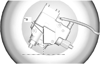
*a Valve Edge As shown in the illustration, adjust the position of the No. 2 hydrogen tank assembly so that its valve edge is in the vertical direction.
-
Using the engine sling device and belt, hoist up the No. 2 hydrogen tank assembly.
Note
Do not allow the No. 2 hydrogen tank assembly to fall.
-
*a Upper View *b Lower View *c Side View *d SST (Support No. 6) *e Make sure there is no gap. As shown in the illustration, slowly press the valve edge of the No. 2 hydrogen tank assembly against the SST (support No. 6), and set the No. 2 hydrogen tank assembly to the 2 rear hydrogen tank frame sub-assemblies.
- SST
- 09403-62010 ( 09403-06060 )
Note
-
To prevent the rubber sheet from being moved out of position, perform positioning with the No. 2 hydrogen tank assembly lifted up.
-
Make sure that there is no gap between the valve edge of the No. 2 hydrogen tank assembly and the SST (support No. 6).
-
*a Hinge *b Detent Temporarily tighten the 2 rear hydrogen tank band sub-assemblies to the 2 rear hydrogen tank frame sub-assemblies with the 2 bolts.
Note
Make sure the hinge does not ride up on the detent.
-
*a Parallel *b Lower View *c SST (Support No. 4) *d Compression Spring *e Bent Flange *f Edge Temporarily tighten the 2 rear hydrogen tank band sub-assemblies with the 2 bolts, 2 rear hydrogen tank spring bolt cups and 2 compression springs.
- SST
- 09403-62010 ( 09403-06040 )
Note
-
Set the rear hydrogen tank band sub-assembly parallel with the rear hydrogen tank frame sub-assembly.
-
Make sure the compression spring does not ride up onto the bent flange of the rear hydrogen tank frame sub-assembly.
-
Install so that the edge of the rear hydrogen tank spring bolt cup and the SST (support No. 4) are parallel.
-
*a for LH Side *b for RH Side *c Hold Fully tighten the bolt (A) (hinge side).
- Torque:
- 50 N*m { 510 kgf*cm, 37 ft.*lbf }
-
Fully tighten the bolt (B) (compression spring side).
- Torque:
- 50 N*m { 510 kgf*cm, 37 ft.*lbf }
Note
-
After tightening the LH side, tighten the RH side.
-
While holding the rear hydrogen tank spring bolt cup, tighten the bolt.
-
*a Upper View *b Lower View *c Side View *d SST (Support No. 6) *e Make sure there is no gap. Check that there is no gap between the valve edge of the No. 2 hydrogen tank assembly and the SST (support No. 5).
- SST
- 09403-62010 ( 09403-06060 )
Note
If there is a gap, loosen the rear hydrogen tank band sub-assembly and re-adjust the positioning of the No. 2 hydrogen tank assembly.
-
*a SST (Support No. 6) *b SST (Nut) Remove the SST (nuts) and SST (support No. 6).
- SST
- 09403-62010 ( 09403-06060, 09403-06090 )
-
-
INSTALL FUEL TUBE GROMMET
-
Engage the claw and install a new fuel tube grommet to the front hydrogen tank frame sub-assembly LH.
-
-
TEMPORARILY TIGHTEN NO. 2 HYDROGEN TANK TUBE
Note
To prevent damage to seal portions or threaded portions, and to prevent openings from being contaminated by dust, metal fragments, etc., do not remove the protective caps of piping connection areas included with new parts until immediately before performing the procedure.
-
Engage the clamp and install the No. 2 hydrogen tank tube to the fuel tube grommet.
-
To prevent damage to seal portions or threaded portions, and to prevent openings from being contaminated by dust, metal fragments, etc., do not remove the protective tape from the seal portions, threaded portions, and openings of the No. 1 hydrogen tank assembly and hydrogen tank tube joint until immediately before performing the procedure.
Note
When frost has formed on the hydrogen tank assembly or piping, water droplets may be formed when the frost begins to melt. If water droplets enter the tank or piping, it could result in blockage of the hydrogen piping, so do not allow water droplets to enter the tank or piping.
-
To prevent damage to the seal portions and threaded portions, and to prevent foreign matter such as dust or metal fragments from entering the openings, do not remove the protective caps of the new No. 2 hydrogen tank tube until immediately before performing work.
Note
When frost has formed on the hydrogen tank assembly or piping, water droplets may be formed when the frost begins to melt. If water droplets enter the tank or piping, it could result in blockage of the hydrogen piping, so do not allow water droplets to enter the tank or piping.
-
Temporarily tighten the No. 2 hydrogen tank tube to the No. 1 hydrogen tank assembly and hydrogen tank tube joint with the 2 union nuts.
-
-
TEMPORARILY TIGHTEN NO. 4 HYDROGEN TANK TUBE
Note
To prevent damage to seal portions or threaded portions, and to prevent openings from being contaminated by dust, metal fragments, etc., do not remove the protective caps of piping connection areas included with new parts until immediately before performing the procedure.
-
Engage the clamp and install the No. 4 hydrogen tank tube to the fuel tube grommet.
-
To prevent damage to seal portions or threaded portions, and to prevent openings from being contaminated by dust, metal fragments, etc., do not remove the protective tape from the seal portions, threaded portions, and openings of the No. 1 hydrogen tank assembly and hydrogen tank tube joint until immediately before performing the procedure.
Note
When frost has formed on the hydrogen tank assembly or piping, water droplets may be formed when the frost begins to melt. If water droplets enter the tank or piping, it could result in blockage of the hydrogen piping, so do not allow water droplets to enter the tank or piping.
-
To prevent damage to the seal portions and threaded portions, and to prevent foreign matter such as dust or metal fragments from entering the openings, do not remove the protective caps of the new No. 4 hydrogen tank tube until immediately before performing work.
Note
When frost has formed on the hydrogen tank assembly or piping, water droplets may be formed when the frost begins to melt. If water droplets enter the tank or piping, it could result in blockage of the hydrogen piping, so do not allow water droplets to enter the tank or piping.
-
Temporarily tighten the No. 4 hydrogen tank tube to the No. 1 hydrogen tank assembly and hydrogen tank tube joint with the 2 union nuts.
-
-
FULLY TIGHTEN NO. 2 HYDROGEN TANK TUBE
-
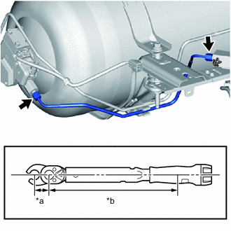
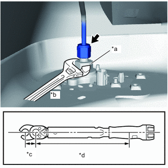
*a 17 mm Union Nut Wrench Fulcrum Length *b Torque Wrench Fulcrum Length Using a 17 mm union nut wrench, fully tighten the 2 union nuts.
- Torque:
- Specified tightening torque
- 25 N*m { 255 kgf*cm, 18 ft.*lbf }
Note
To prevent the tube from turning together, hold the tube in place while tightening the union nut.
Tech Tips
-
Calculate the torque wrench reading when changing the fulcrum length of the torque wrench.
-
When using 17 mm union nut wrench (fulcrum length of 30 mm (1.18 in.)) + torque wrench (fulcrum length of 255 mm (10.0 in.)):
22 N*m (224 kgf*cm, 16 ft.*lbf)
-
-
FULLY TIGHTEN NO. 4 HYDROGEN TANK TUBE
-
*a 17 mm Union Nut Wrench Fulcrum Length *b Torque Wrench Fulcrum Length Using a 17 mm union nut wrench, fully tighten the 2 union nuts.
- Torque:
- Specified tightening torque
- 25 N*m { 255 kgf*cm, 18 ft.*lbf }
Note
To prevent the tube from turning together, hold the tube in place while tightening the union nut.
Tech Tips
-
Calculate the torque wrench reading when changing the fulcrum length of the torque wrench.
-
When using 17 mm union nut wrench (fulcrum length of 30 mm (1.18 in.)) + torque wrench (fulcrum length of 255 mm (10.0 in.)):
22 N*m (224 kgf*cm, 16 ft.*lbf)
-
-
TEMPORARILY TIGHTEN NO. 5 HYDROGEN TANK TUBE
Note
To prevent damage to seal portions or threaded portions, and to prevent openings from being contaminated by dust, metal fragments, etc., do not remove the protective caps of piping connection areas included with new parts until immediately before performing the procedure.
-
To prevent damage to seal portions or threaded portions, and to prevent openings from being contaminated by dust, metal fragments, etc., do not remove the protective tape from the seal portions, threaded portions, and openings of the No. 2 hydrogen tank assembly and hydrogen tank tube joint until immediately before performing the procedure.
Note
When frost has formed on the hydrogen tank assembly or piping, water droplets may be formed when the frost begins to melt. If water droplets enter the tank or piping, it could result in blockage of the hydrogen piping, so do not allow water droplets to enter the tank or piping.
-
To prevent damage to the seal portions and threaded portions, and to prevent foreign matter such as dust or metal fragments from entering the openings, do not remove the protective caps of the new No. 5 hydrogen tank tube until immediately before performing work.
Note
When frost has formed on the hydrogen tank assembly or piping, water droplets may be formed when the frost begins to melt. If water droplets enter the tank or piping, it could result in blockage of the hydrogen piping, so do not allow water droplets to enter the tank or piping.
-
Temporarily tighten the No. 5 hydrogen tank tube to the No. 2 hydrogen tank assembly and hydrogen tank tube joint with the 2 union nuts.
-
-
TEMPORARILY TIGHTEN NO. 3 HYDROGEN TANK TUBE
Note
To prevent damage to seal portions or threaded portions, and to prevent openings from being contaminated by dust, metal fragments, etc., do not remove the protective caps of piping connection areas included with new parts until immediately before performing the procedure.
-
To prevent damage to seal portions or threaded portions, and to prevent openings from being contaminated by dust, metal fragments, etc., do not remove the protective tape from the seal portions, threaded portions, and openings of the No. 2 hydrogen tank assembly and hydrogen tank tube joint until immediately before performing the procedure.
Note
When frost has formed on the hydrogen tank assembly or piping, water droplets may be formed when the frost begins to melt. If water droplets enter the tank or piping, it could result in blockage of the hydrogen piping, so do not allow water droplets to enter the tank or piping.
-
To prevent damage to the seal portions and threaded portions, and to prevent foreign matter such as dust or metal fragments from entering the openings, do not remove the protective caps of the new No. 3 hydrogen tank tube until immediately before performing work.
Note
When frost has formed on the hydrogen tank assembly or piping, water droplets may be formed when the frost begins to melt. If water droplets enter the tank or piping, it could result in blockage of the hydrogen piping, so do not allow water droplets to enter the tank or piping.
-
Temporarily tighten the No. 3 hydrogen tank tube to the No. 2 hydrogen tank assembly and hydrogen tank tube joint with the 2 union nuts.
-
-
TEMPORARILY TIGHTEN HYDROGEN TANK TUBE ASSEMBLY
Note
To prevent damage to seal portions or threaded portions, and to prevent openings from being contaminated by dust, metal fragments, etc., do not remove the protective caps of piping connection areas included with new parts until immediately before performing the procedure.
-
To prevent damage to seal portions or threaded portions, and to prevent openings from being contaminated by dust, metal fragments, etc., do not remove the protective tape from the seal portions, threaded portions, and openings of the hydrogen tank tube joint until immediately before performing the procedure.
Note
When frost has formed on the hydrogen tank assembly or piping, water droplets may be formed when the frost begins to melt. If water droplets enter the tank or piping, it could result in blockage of the hydrogen piping, so do not allow water droplets to enter the tank or piping.
-
To prevent damage to the seal portions and threaded portions, and to prevent foreign matter such as dust or metal fragments from entering the openings, do not remove the protective caps of the new hydrogen tank tube assembly (hydrogen tank tube joint) until immediately before performing work.
Note
When frost has formed on the hydrogen tank assembly or piping, water droplets may be formed when the frost begins to melt. If water droplets enter the tank or piping, it could result in blockage of the hydrogen piping, so do not allow water droplets to enter the tank or piping.
-
Temporarily tighten the hydrogen tank tube assembly to the hydrogen tank tube joint with the union nut.
-
-
INSTALL FUEL TUBE GROMMET
-
Engage the 2 clamps and install 2 new fuel tube grommets to the hydrogen tank tube assembly and the No. 3 hydrogen tank tube.
Note
-
Be careful not to damage or deform the high pressure hydrogen piping.
-
If the pipe protector material of the high pressure hydrogen piping is damaged so that the internal pipe itself becomes visible, replace the high pressure hydrogen piping with a new one.
-
-
-
INSTALL NO. 1 FUEL TUBE CLAMP
-
Engage the 3 clamps and install a new No. 1 fuel tube clamp to the hydrogen tank tube assembly, No. 3 hydrogen tank tube and No. 5 hydrogen tank tube.
Note
-
Be careful not to damage or deform the high pressure hydrogen piping.
-
If the pipe protector material of the high pressure hydrogen piping is damaged so that the internal pipe itself becomes visible, replace the high pressure hydrogen piping with a new one.
-
-
-
INSTALL HYDROGEN TANK TUBE CLAMP BRACKET
-
Install the hydrogen tank tube clamp bracket to the No. 1 fuel tube clamp.
Note
-
Be careful not to damage or deform the high pressure hydrogen piping.
-
If the pipe protector material of the high pressure hydrogen piping is damaged so that the internal pipe itself becomes visible, replace the high pressure hydrogen piping with a new one.
-
-
-
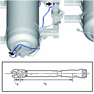
FULLY TIGHTEN NO. 5 HYDROGEN TANK TUBE
-
*a Cloth, etc. *b 17 mm Union Nut Wrench Fulcrum Length *c Torque Wrench Fulcrum Length Tightly insert a piece of cloth, etc. in the location shown in the illustration.
Tech Tips
This is done to prevent the tube from rotating together when tightening the union nut, which would cause the clearance between the No. 5 hydrogen tank tube and the hydrogen supply regulator assembly to become smaller.
-
Using a 17 mm union nut wrench, fully tighten the 2 union nuts.
- Torque:
- Specified tightening torque
- 25 N*m { 255 kgf*cm, 18 ft.*lbf }
Note
To prevent the tube from turning together, hold the tube in place while tightening the union nut.
Tech Tips
-
Calculate the torque wrench reading when changing the fulcrum length of the torque wrench.
-
When using 17 mm union nut wrench (fulcrum length of 30 mm (1.18 in.)) + torque wrench (fulcrum length of 255 mm (10.0 in.)):
22 N*m (224 kgf*cm, 16 ft.*lbf)
-
Remove the cloth, etc.
-
-
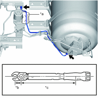
FULLY TIGHTEN NO. 3 HYDROGEN TANK TUBE
-
*a Cloth, etc. *b 17 mm Union Nut Wrench Fulcrum Length *c Torque Wrench Fulcrum Length Tightly insert a piece of cloth, etc. in the location shown in the illustration.
Tech Tips
This is done to prevent the tube from rotating together when tightening the union nut, which would cause the clearance between the No. 3 hydrogen tank tube and the No. 2 hydrogen tank assembly to become smaller, and to prevent misalignment of the pathway between the hydrogen tank tube assembly, No. 3 hydrogen tank tube and No. 5 hydrogen tank tube, which are held in place by the fuel tube grommet and No. 1 fuel tube clamp.
-
Using a 17 mm union nut wrench, fully tighten the 2 union nuts.
- Torque:
- Specified tightening torque
- 25 N*m { 255 kgf*cm, 18 ft.*lbf }
Note
To prevent the tube from turning together, hold the tube in place while tightening the union nut.
Tech Tips
-
Calculate the torque wrench reading when changing the fulcrum length of the torque wrench.
-
When using 17 mm union nut wrench (fulcrum length of 30 mm (1.18 in.)) + torque wrench (fulcrum length of 255 mm (10.0 in.)):
22 N*m (224 kgf*cm, 16 ft.*lbf)
-
Remove the cloth, etc.
-
-
FULLY TIGHTEN HYDROGEN TANK TUBE ASSEMBLY
-
*a 17 mm Union Nut Wrench Fulcrum Length *b Torque Wrench Fulcrum Length Using a 17 mm union nut wrench, fully tighten the union nut.
- Torque:
- Specified tightening torque
- 25 N*m { 255 kgf*cm, 18 ft.*lbf }
Note
To prevent the tube from turning together, hold the tube in place while tightening the union nut.
Tech Tips
-
Calculate the torque wrench reading when changing the fulcrum length of the torque wrench.
-
When using 17 mm union nut wrench (fulcrum length of 30 mm (1.18 in.)) + torque wrench (fulcrum length of 255 mm (10.0 in.)):
22 N*m (224 kgf*cm, 16 ft.*lbf)
-
-
INSTALL WIRE HARNESS CLAMP
-
No. 1 Hydrogen Tank Assembly Side:
-
Engage the clamp and install the wire harness clamp to the wire harness of the No. 1 hydrogen tank assembly and No. 4 hydrogen tank tube sub-assembly.
-
-
No. 2 Hydrogen Tank Assembly Side:
-
Engage the clamp and install the wire harness clamp to the wire harness of the No. 2 hydrogen tank assembly and hydrogen tank tube sub-assembly.
-
Engage the clamp and connect the No. 2 hydrogen tank assembly connector to the hydrogen tank tube clamp bracket.
-
-
-
INSTALL NO. 2 HYDROGEN SUPPLY TUBE SUB-ASSEMBLY
-
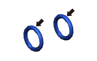
Apply a light coat of TOYOTA Genuine FC Grease to 2 new O-rings.
-
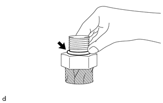
To prevent contamination by foreign matter, remove the protective tape from the openings of the No. 2 hydrogen supply tube sub-assembly immediately before performing the procedure.
Note
When frost has formed on the hydrogen tank assembly or piping, water droplets may be formed when the frost begins to melt. If water droplets enter the tank or piping, it could result in blockage of the hydrogen piping, so do not allow water droplets to enter the tank or piping.
-
Install the 2 O-rings to the No. 2 hydrogen supply tube sub-assembly.
Note
During installation, do not damage the O-ring.
-
To prevent contamination by foreign matter, remove the protective tape from the openings of the hydrogen supply regulator assembly immediately before performing the procedure.
Note
When frost has formed on the hydrogen tank assembly or piping, water droplets may be formed when the frost begins to melt. If water droplets enter the tank or piping, it could result in blockage of the hydrogen piping, so do not allow water droplets to enter the tank or piping.
-
Install the No. 2 hydrogen supply tube sub-assembly to the hydrogen supply regulator assembly with the bolts.
- Torque:
- 8.5 N*m { 87 kgf*cm, 75 in.*lbf }
Note
Make sure the O-ring and the piping connecting portion are not damaged and have no foreign matter adhering.
-
-
INSTALL HYDROGEN TANK UNIT
-
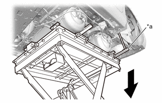
Operate the engine lifter and slowly install the hydrogen tank unit to the vehicle.
Note
Make sure the hydrogen tank assembly and high pressure hydrogen piping do not interfere with the vehicle body or surrounding components.
-
Temporarily tighten the hydrogen tank unit to the vehicle with the 8 bolts.
-
Fully tighten the 8 bolts.
- Torque:
- 85 N*m { 867 kgf*cm, 63 ft.*lbf }
-
*a SST (Tank Belt Fixture) *b SST (Bolt) Remove the SST (bolts) and each SST (tank belt fixture).
- SST
- 09403-62010 ( 09403-06100, 09403-06110 )
-
*a SST (Hydrogen Tank Stand) Remove the SST (hydrogen tank stand).
- SST
- 09403-62010
-
-
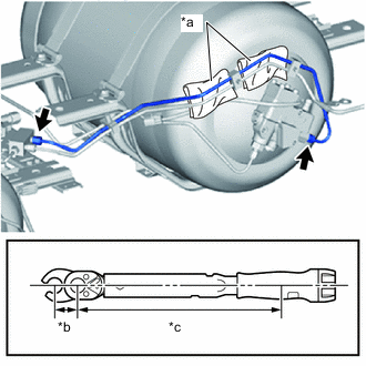
CONNECT HYDROGEN TANK TUBE ASSEMBLY
-
To prevent damage to the seal portions and threaded portions, and to prevent foreign matter such as dust or metal fragments from entering the openings, do not remove the protective tape of the hydrogen inlet receptacle assembly until immediately before performing work.
Note
When frost has formed on the hydrogen tank assembly or piping, water droplets may be formed when the frost begins to melt. If water droplets enter the tank or piping, it could result in blockage of the hydrogen piping, so do not allow water droplets to enter the tank or piping.
-
To prevent damage to the seal portions and threaded portions, and to prevent foreign matter such as dust or metal fragments from entering the openings, do not remove the protective caps of the new hydrogen tank tube assembly (hydrogen inlet receptacle assembly) until immediately before performing work.
Note
When frost has formed on the hydrogen tank assembly or piping, water droplets may be formed when the frost begins to melt. If water droplets enter the tank or piping, it could result in blockage of the hydrogen piping, so do not allow water droplets to enter the tank or piping.
-
Temporarily tighten the hydrogen tank tube assembly to the hydrogen inlet receptacle assembly with the union nut.
-
Connect the bracket of the hydrogen tank tube assembly to the vehicle with the bolt.
- Torque:
- 22 N*m { 224 kgf*cm, 16 ft.*lbf }
Note
When tightening the bolt, to prevent the high pressure hydrogen piping from rotating together and being strained, hold the bracket portion of the hydrogen tank tube assembly in place by hand while performing the procedure.
-
*a Adapter *b Hold *c 17 mm Union Nut Wrench Fulcrum Length *d Torque Wrench Fulcrum Length Using a 17 mm union nut wrench, fully tighten the union nut.
- Torque:
- Specified tightening torque
- 25 N*m { 255 kgf*cm, 18 ft.*lbf }
Note
Use an adjustable wrench to hold the adapter of the hydrogen inlet receptacle assembly while tightening the union nut.
Tech Tips
-
Calculate the torque wrench reading when changing the fulcrum length of the torque wrench.
-
When using 17 mm union nut wrench (fulcrum length of 30 mm (1.18 in.)) + torque wrench (fulcrum length of 255 mm (10.0 in.)):
22 N*m (224 kgf*cm, 16 ft.*lbf)
-
-
CONNECT HYDROGEN TANK TUBE CLAMP BRACKET
-
Connect the hydrogen tank tube clamp bracket to the vehicle with the bolt.
- Torque:
- 13 N*m { 133 kgf*cm, 10 ft.*lbf }
Note
When tightening the bolt, to prevent the high pressure hydrogen piping from rotating together and being strained, hold the hydrogen tank tube clamp bracket in place by hand while performing the procedure.
-
-
INSTALL WIRING HARNESS CLAMP BRACKET
-
Install the wire harness clamp bracket to the front hydrogen tank frame sub-assembly LH with the bolt.
- Torque:
- 12.5 N*m { 127 kgf*cm, 9 ft.*lbf }
-
Connect the No. 2 hydrogen supply tube sub-assembly to the wire harness clamp bracket with the bolt.
- Torque:
- 8.5 N*m { 87 kgf*cm, 75 in.*lbf }
-
-
CONNECT NO. 1 HYDROGEN SUPPLY TUBE SUB-ASSEMBLY
-
Apply a light coat of TOYOTA Genuine FC Grease to 2 new O-rings.
-
To prevent contamination by foreign matter, remove the protective tape from the openings of the No. 1 hydrogen supply tube sub-assembly immediately before performing the procedure.
Note
When frost has formed on the hydrogen tank assembly or piping, water droplets may be formed when the frost begins to melt. If water droplets enter the tank or piping, it could result in blockage of the hydrogen piping, so do not allow water droplets to enter the tank or piping.
-
Install the 2 O-rings to the No. 1 hydrogen supply tube sub-assembly.
Note
During installation, do not damage the O-ring.
-
To prevent contamination by foreign matter, remove the protective tape from the openings of the No. 2 hydrogen supply tube sub-assembly immediately before performing the procedure.
Note
When frost has formed on the hydrogen tank assembly or piping, water droplets may be formed when the frost begins to melt. If water droplets enter the tank or piping, it could result in blockage of the hydrogen piping, so do not allow water droplets to enter the tank or piping.
-
Connect the No. 1 hydrogen supply tube sub-assembly to the No. 2 hydrogen supply tube sub-assembly with the bolt.
- Torque:
- 8.5 N*m { 87 kgf*cm, 75 in.*lbf }
Note
Make sure the O-ring and the engagement portion are not damaged and have no foreign matter adhering.
-
-
CONNECT NO. 2 HYDROGEN SUPPLY TUBE SUB-ASSEMBLY
-
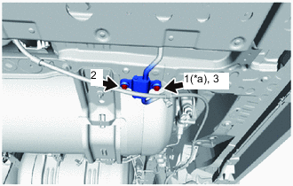
*a Temporarily Tighten Connect the No. 2 hydrogen supply tube sub-assembly to the vehicle with the 2 bolts in the sequence shown in the illustration.
- Torque:
- 8.5 N*m { 87 kgf*cm, 75 in.*lbf }
-
-
CONNECT NO. 3 FLOOR WIRE
-
Engage the 8 clamps and connect the No. 3 floor wire to the front center hydrogen tank frame and wire harness clamp bracket.
-
Connect the 2 hydrogen tank pressure sensor connectors.
-
Connect the height control sensor sub-assembly connector.
-
Connect the hydrogen detector connector.
-
Engage the clamp and connect the No. 3 floor wire to the hydrogen tank tube clamp bracket.
-
Connect the No. 2 hydrogen tank assembly connector.
-
Engage the clamp and connect the No. 1 hydrogen tank assembly connector to the wire harness clamp bracket.
-
Connect the No. 1 hydrogen tank assembly connector.
-
-
CONNECT CABLE FROM NEGATIVE AUXILIARY BATTERY TERMINAL
-
INSTALL LUGGAGE TRIM SERVICE HOLE COVER
-
FIRST LEAK CHECK
Tech Tips
-
The primary leak inspection is performed using nitrogen gas when hydrogen system components are replaced or installed/removed, after installing the hydrogen tank unit to the vehicle and connecting the hydrogen piping.
-
When performing primary leak inspection, perform it with the floor covers and rear wheel house plate removed, so that the hydrogen tank assemblies and hydrogen piping are visible.
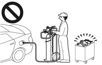
CAUTION:
-
When performing the primary leak inspection, do not perform procedures without wearing protective glasses and gloves.
-
High pressure nitrogen gas could cause a serious accident.
Note
After performing the primary leak inspection and confirming that there are no leaks, perform secondary leak inspection by filling compressed hydrogen gas at a hydrogen station. When performing secondary leak inspection, the vehicle cannot be driven to the hydrogen station under its own power, so transport it using a car carrier, etc.
-
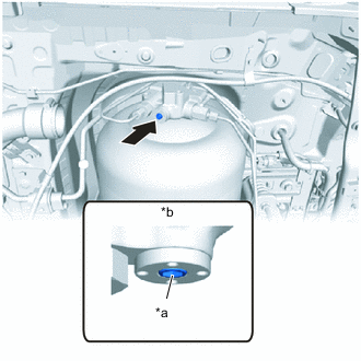
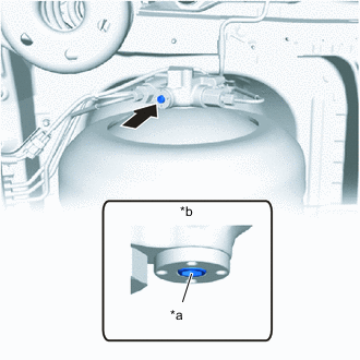
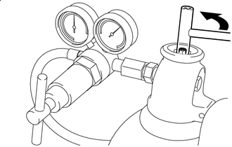
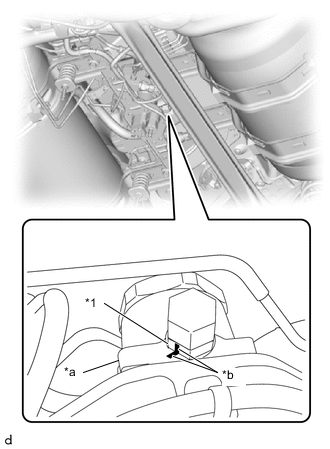
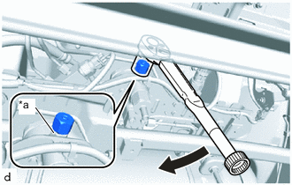
*a Adjustment Bolt *b Manual Valve Closed Using an 8 mm socket hexagon wrench, apply the specified tightening torque to the adjustment bolt to make sure the manual valve of the No. 1 hydrogen tank assembly is closed.
- Torque:
- 20 N*m { 204 kgf*cm, 15 ft.*lbf }
Note
-
The manual valve shuts off the pressure from the hydrogen tank assembly, so be careful not to damage the hexagonal portion.
-
If the hexagonal portion has been damaged, the No. 1 hydrogen tank assembly must be replaced.
-
To prevent nitrogen gas from flowing into the hydrogen tank assembly, do not open the manual valve until after the primary leak inspection is completed.
-
*a Adjustment Bolt *b Manual Valve Closed Using an 8 mm socket hexagon wrench, apply the specified tightening torque to the adjustment bolt to make sure the manual valve of the No. 2 hydrogen tank assembly is closed.
- Torque:
- 20 N*m { 204 kgf*cm, 15 ft.*lbf }
Note
-
The manual valve shuts off the pressure from the hydrogen tank assembly, so be careful not to damage the hexagonal portion.
-
If the hexagonal portion has been damaged, the No. 1 hydrogen tank assembly must be replaced.
-
To prevent nitrogen gas from flowing into the hydrogen tank assembly, do not open the manual valve until after the primary leak inspection is completed.
-
Prepare the SST (10 MPa (102.0 kgf/cm2, 1450 psi) leak inspection tool).
-
*a SST (Port Assy) *b Injection Valve closed condition *c Discharge Valve closed condition Check that the injection valve and discharge valve of the SST (port assy) are closed.
- SST
- 09402-62010 ( 09402-06020 )
-
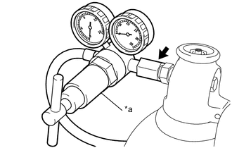
*a SST (Regulator Assy) Connect the SST (regulator assy) to a nitrogen cylinder.
- SST
- 09402-62010 ( 09402-06010 )
Note
-
Wrap the threaded portion with seal tape.
-
Securely tighten so that nitrogen gas will not leak out.
-
-
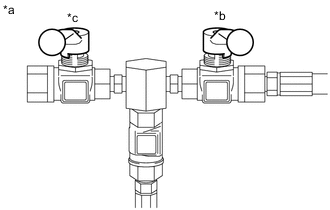
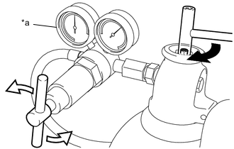
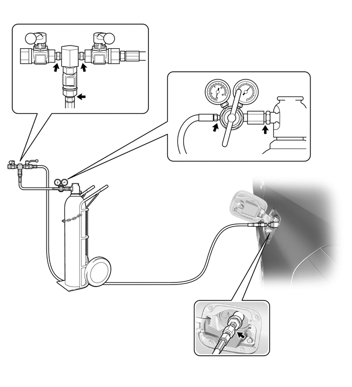
Connect the nitrogen cylinder to the hydrogen inlet receptacle assembly via the SST (regulator assy).
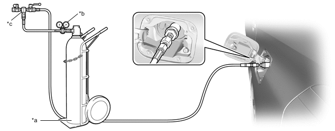
*a Nitrogen Cylinder *b SST (Regulator Assy) *c SST (Port Assy) - - - SST
- 09402-62010 ( 09402-06010, 09402-06020 )
Note
-
Leave the nitrogen regulator valve closed.
-
The internal volume from the cylinder to the nozzle should be 130 cc or less.
-
The smallest marking of the pressure system should be 0.2 MPa (2.0 kgf/cm2, 29 psi) or less.
-

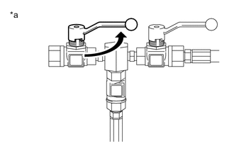
Open the Nitrogen Cylinder Valve Slowly open the nitrogen cylinder valve.
-
*a SST (Port Assy) Slowly Open Slowly open the injection valve of the SST (port assy).
- SST
- 09402-62010 ( 09402-06020 )
-
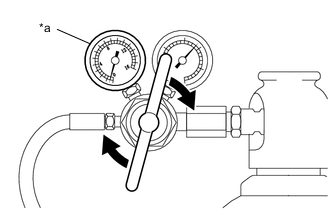
*a SST (Regulator Assy) Open the Nitrogen Cylinder Valve Slowly rotate the handle of the SST (regulator assy) in the clockwise direction to open the valve, and let the pressure rise to 10 MPa (102.0 kgf/cm2, 1450 psi).
- SST
- 09402-62010 ( 09402-06010 )
Note
-
Raise the pressure to 10 MPa (102.0 kgf/cm2, 1450 psi) over a period of 5 to 20 seconds.
-
If there is a hissing sound of nitrogen gas leaking out when the tank shut valves are opened, close both tank shut valves, and after determining the location of the leak, replace the leaking component with a new one.
-
Even when it seem like the leaking sound is only coming from one location, it may be drowning out leaking sounds from other locations, so make sure to perform leakage point identification for all connecting portions.
-
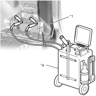
*1 Auxiliary Battery *a Battery Charger Connect a battery charger to the auxiliary battery, and put the auxiliary battery into a charging state.
Tech Tips
This is done to prevent the auxiliary battery from becoming discharged, as the tank shut valve of the hydrogen tank assembly will be forced to operate for 30 minutes.
-
Using the GTS, enter the following menus: Body Electrical / Power Source Control / Utility / Auto Power OFF Cancel
Body Electrical > Power Source Control > UtilityTester Display Auto Power OFF Cancel -
Open the tank shut valves of the No. 1 hydrogen tank assembly and No. 2 hydrogen tank assembly.
Note
-
If the Data List item "Medium-range Hydrogen Pressure (gauge)" decreases to below 0.6 MPa (6.1 kgf/cm2, 87 psi) the tank shut valves of the No. 1 and No. 2 hydrogen tank assemblies will forcibly close.
-
If there is a hissing sound of nitrogen gas leaking out when the tank shut valves are opened, close both tank shut valves, and after determining the location of the leak, replace the leaking component with a new one.
-
Even when it seem like the leaking sound is only coming from one location, it may be drowning out leaking sounds from other locations, so make sure to perform leakage point identification for all connecting portions.
-
-
If the tank shut valves of the No. 1 and No. 2 hydrogen tank assemblies do not open, open the tank shut valves again.
-
When the tank shut valve has been opened, if the pressure has gone below 10 MPa (102.0 kgf/cm2, 1450 psi), increase the pressure to 10 MPa (102.0 kgf/cm2, 1450 psi).
-
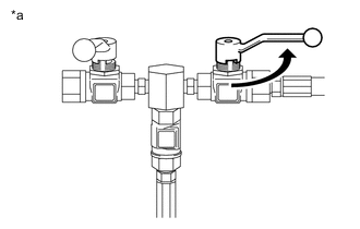
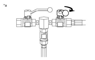
*a SST (Regulator Assy) Close the Nitrogen Cylinder Valve 
Close the SST (Regulator Assy) Valve Close the nitrogen cylinder valve.
-
Rotate the handle of the SST (regulator assy) in the counterclockwise direction to close the valve.
- SST
- 09402-62010 ( 09402-06010 )
-
After closing the nitrogen cylinder valve and the SST (regulator assy) valve, wait for 10 minutes to allow the pressure in the piping to stabilize.
Tech Tips
When nitrogen has just been filled, the temperature inside the piping is increased, causing pressure to increase. Afterwards, when the temperature in the piping decreases, the pressure decreases. For this reason, pressure is not stable immediately after nitrogen filling.
-
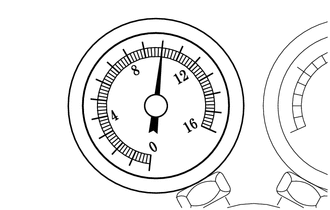
After checking that the pressure gauge has stabilized, wait an additional 30 minutes, and then check the pressure gauge.
OK Pressure decrease is 0.2 MPa (2.0 kgf/cm2, 29 psi) or less
-
When the pressure decrease is 0.2 MPa (2.0 kgf/cm2, 29 psi) or less (Go to "When pressure decrease is 0.2 MPa (2.0 kgf/cm2, 29 psi) or less")
-
When the pressure decrease is 0.2 MPa (2.0 kgf/cm2, 29 psi) or higher (Go to "When pressure decrease is more than 0.2 MPa (2.0 kgf/cm2, 29 psi)")
-
-
When pressure decrease is 0.2 MPa (2.0 kgf/cm2, 29 psi) or less
-
*a SST (Port Assy) Open the Discharge Valve of the SST (Port Assy) Slowly open the discharge valve of the SST (port assy) to depressurize the nitrogen gas.
- SST
- 09402-62010 ( 09402-06020 )
Note
Keep your hands and face away from the discharge port.
-
*a SST (Regulator Assy) Open the SST (Regulator Assy) Valve Slowly rotate the handle of the SST (regulator assy) a small amount in the clockwise direction to open the valve.
- SST
- 09402-62010 ( 09402-06010 )
Tech Tips
This is done to reduce the pressure of the nitrogen gas between the nitrogen cylinder and SST (regulator assy).
-
*a SST (Port Assy) Close the Injection Valve of the SST (Port Assy) Close the injection valve of the SST (port assy).
- SST
- 09402-62010 ( 09402-06020 )
-
*a SST (Port Assy) Close the Discharge Valve of the SST (Port Assy) Close the discharge valve of the SST (port assy).
- SST
- 09402-62010 ( 09402-06020 )
-
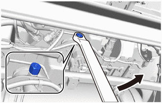
*1 Hydrogen Supply Regulator Union *a Body *b Paint Mark Apply paint marks to the hydrogen supply regulator union and the body of the hydrogen supply regulator assembly as shown in the illustration.
Tech Tips
When loosening the No. 1 hydrogen supply regulator plug, there is a possibility that the hydrogen supply regulator union could turn together with it and be loosened, so applying paint marks will enable judgment of whether the hydrogen supply regulator union has been loosened.
-
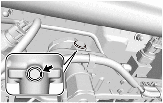
Slowly loosen the No. 1 hydrogen supply regulator plug until the hissing sound of gas escaping can be heard, then stop loosening the No. 1 hydrogen supply regulator plug and wait for the sound to stop. Repeat this procedure multiple times until the sound stops occurring, in order to depressurize the compressed hydrogen gas from the medium pressure leak check port of the hydrogen supply regulator assembly.
Note
When depressurizing the nitrogen gas, only loosen the No. 1 hydrogen supply regulator plug. Do not remove it.
-
Remove the No. 1 hydrogen supply regulator plug from the hydrogen supply regulator union.
Note
When frost has formed on the hydrogen tank assembly or piping, water droplets may be formed when the frost begins to melt. If water droplets enter the tank or piping, it could result in blockage of the hydrogen piping, so do not allow water droplets to enter the tank or piping.
-
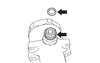
Remove the O-ring from the hydrogen supply regulator union.
-
*a Protective Tape To prevent damage to the seal portions and threaded portions, and to prevent foreign matter such as dust or metal fragments from entering the openings, cover the seal portions, threaded portions, and openings of the hydrogen supply regulator union with protective tape.
-
*a Correct *b Incorrect *c Paint Mark Check that the hydrogen supply regulator union has not been loosened.
Tech Tips
If the hydrogen supply regulator union has been loosened, there is the possibility of a compressed hydrogen gas leak, so it is necessary to remove the hydrogen supply regulator union and replace the O-ring with a new one.
-
Procedures for when the hydrogen supply regulator union has been loosened:
-
Remove the hydrogen supply regulator union.
Note
When frost has formed on the hydrogen tank assembly or piping, water droplets may be formed when the frost begins to melt. If water droplets enter the tank or piping, it could result in blockage of the hydrogen piping, so do not allow water droplets to enter the tank or piping.
-
*a Protective Tape To prevent foreign matter such as dust or metal fragments from entering the openings, cover the seal portions, threaded portions, and openings of the hydrogen supply regulator union installation portion with protective tape.
-
Remove the O-ring from the hydrogen supply regulator union.
Note
Perform the procedure by hand. Do not use any tools.
-
Clean and degrease the threaded portion of the hydrogen supply regulator union.
-
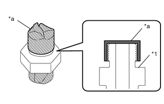
*1 Hydrogen Supply Regulator Union *a Protective Tape To prevent the O-ring from being damaged during installation, apply protective tape as shown in the illustration.
Tech Tips
Cover the hydrogen supply regulator union with protective tape so that the threaded portion and the hole cannot be seen.
-
Coat a new O-ring with TOYOTA Genuine FC Grease.
-
Install the O-ring to the hydrogen supply regulator union.
Note
-
Make sure not to damage the O-ring.
-
Make sure the O-ring is not twisted.
-
-
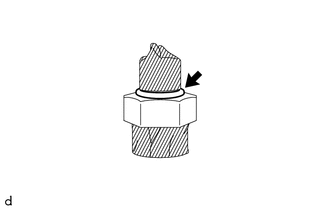
Remove the protective tape from the hydrogen supply regulator union.
Note
When frost has formed on the hydrogen tank assembly or piping, water droplets may be formed when the frost begins to melt. If water droplets enter the tank or piping, it could result in blockage of the hydrogen piping, so do not allow water droplets to enter the tank or piping.
-
Coat the O-ring and the threaded portion of the hydrogen supply regulator union with TOYOTA Genuine FC Grease.
-
To prevent the hydrogen supply regulator union installation portion from being contaminated by dust, metal fragments, etc., do not remove the protective tape from it until immediately before performing the work.
Note
When frost has formed on the hydrogen tank assembly or piping, water droplets may be formed when the frost begins to melt. If water droplets enter the tank or piping, it could result in blockage of the hydrogen piping, so do not allow water droplets to enter the tank or piping.
-
Install the hydrogen supply regulator union.
Torque 41.5 N*m (423 kgf*cm, 31 ft.*lbf) Note
When installing the O-ring, make sure that it is not pinched.
-
-
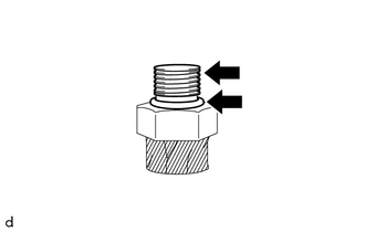
To prevent damage to the seal portions and threaded portions, and to prevent foreign matter such as dust or metal fragments from entering the openings, do not remove the protective tape covering the seal portions, threaded portions, and openings of the hydrogen supply regulator union until immediately before performing work.
Note
When frost has formed on the hydrogen tank assembly or piping, water droplets may be formed when the frost begins to melt. If water droplets enter the tank or piping, it could result in blockage of the hydrogen piping, so do not allow water droplets to enter the tank or piping.
-
Apply TOYOTA Genuine FC Grease to a new O-ring and to the threaded portion of the hydrogen supply regulator union.
-
Install the O-ring to the hydrogen supply regulator union.
Note
During installation, make sure not to damage the O-ring.
-
*a Hexagonal Portion Install the No. 1 hydrogen supply regulator plug to the hydrogen supply regulator union.
- Torque:
- 25 N*m { 255 kgf*cm, 18 ft.*lbf }
-
Close the tank shut valve of the No. 1 hydrogen tank assembly and No. 2 hydrogen tank assembly.
-
Disconnect the nitrogen regulator from the hydrogen inlet receptacle assembly.
-
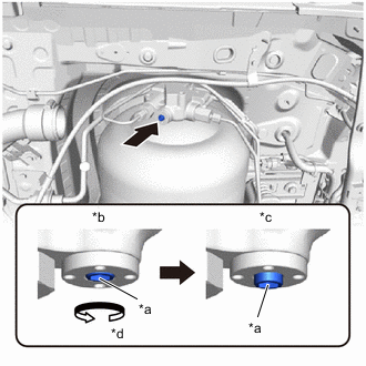
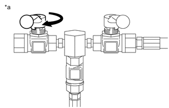
*a Adjustment Bolt *b Manual Valve Closed *c Manual Valve Open *d Counterclockwise Using an 8 mm socket hexagon wrench, rotate the adjustment bolt counterclockwise, and open the No. 1 hydrogen tank assembly manual valve.
Note
-
The manual valve shuts off the pressure from the hydrogen tank assembly, so be careful not to damage the hexagonal portion.
-
If the hexagonal portion is damaged, it will be impossible to operate the adjustment bolt.
-
Do not rotate the adjustment bolt more than 4 rotations.
-
Rotating the adjustment bolt more than 4 rotations could damage the manual valve.
-
If the manual valve is damaged, it will be necessary to replace the No. 1 hydrogen tank assembly.
-
Before opening the manual valve, check that the nitrogen gas contained in the hydrogen piping has been depressurized.
-
-
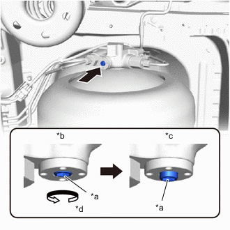
*a Adjustment Bolt *b Manual Valve Closed *c Manual Valve Open *d Counterclockwise Using an 8 mm socket hexagon wrench, rotate the adjustment bolt counterclockwise, and open the No. 2 hydrogen tank assembly manual valve.
Note
-
The manual valve shuts off the pressure from the hydrogen tank assembly, so be careful not to damage the hexagonal portion.
-
If the hexagonal portion is damaged, it will be impossible to operate the adjustment bolt.
-
Do not rotate the adjustment bolt more than 4 rotations.
-
Rotating the adjustment bolt more than 4 rotations could damage the manual valve.
-
If the manual valve is damaged, it will be necessary to replace the No. 2 hydrogen tank assembly.
-
-
-
When pressure decrease is more than 0.2 MPa (2.0 kgf/cm2, 29 psi)
-
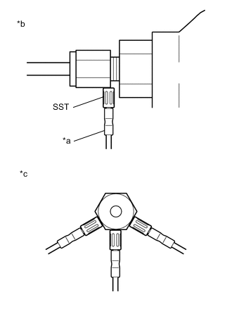
Using soapy water, check the connection points of each component on the vehicle side and on the nitrogen regulator side to determine the locations of the leaks.
Figure 1. <Vehicle-side leak check locations>
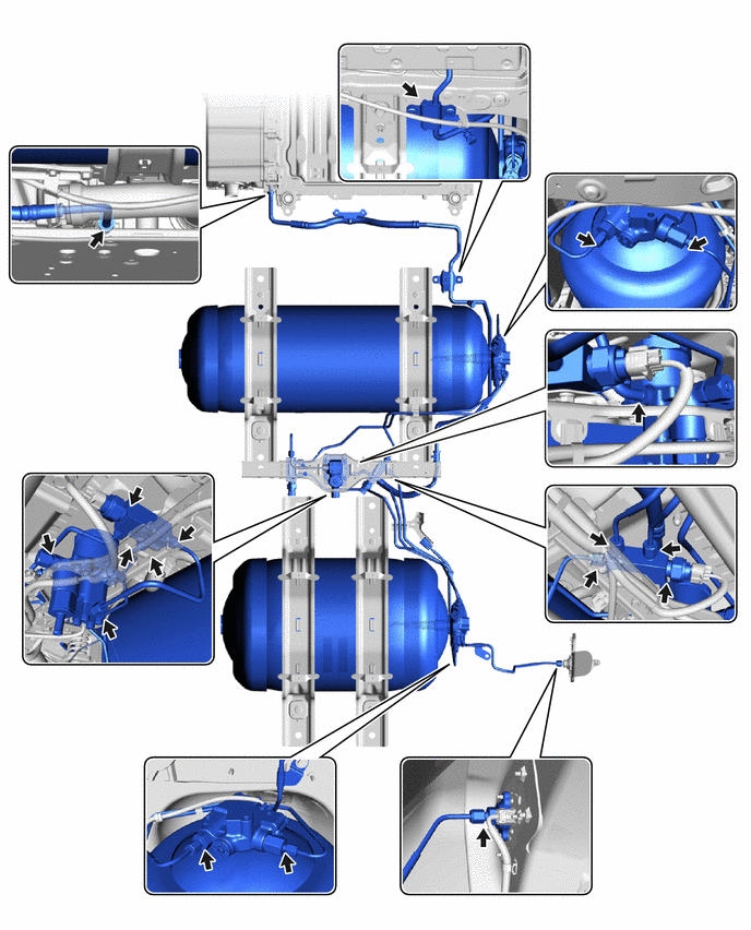
Figure 2. <Nitrogen regulator-side leak check locations>
-
*a SST (Port Assy) Open the Discharge Valve of the SST (Port Assy) Slowly open the discharge valve of the SST (port assy) to depressurize the nitrogen gas.
- SST
- 09402-62010 ( 09402-06020 )
Note
Keep your hands and face away from the discharge port.
-
*a SST (Regulator Assy) Open the SST (Regulator Assy) Valve Slowly rotate the handle of the SST (regulator assy) a small amount in the clockwise direction to open the valve.
- SST
- 09402-62010 ( 09402-06010 )
Tech Tips
This is done to reduce the pressure of the nitrogen gas between the nitrogen cylinder and SST (regulator assy).
-
*a SST (Port Assy) Close the Injection Valve of the SST (Port Assy) Close the injection valve of the SST (port assy).
- SST
- 09402-62010 ( 09402-06020 )
-
*a SST (Port Assy) Close the Discharge Valve of the SST (Port Assy) Close the discharge valve of the SST (port assy).
- SST
- 09402-62010 ( 09402-06020 )
-
*1 Hydrogen Supply Regulator Union *a Body *b Paint Mark Apply paint marks to the hydrogen supply regulator union and the body of the hydrogen supply regulator assembly as shown in the illustration.
Tech Tips
When loosening the No. 1 hydrogen supply regulator plug, there is a possibility that the hydrogen supply regulator union could turn together with it and be loosened, so applying paint marks will enable judgment of whether the hydrogen supply regulator union has been loosened.
-
Slowly loosen the No. 1 hydrogen supply regulator plug until the hissing sound of gas escaping can be heard, then stop loosening the No. 1 hydrogen supply regulator plug and wait for the sound to stop. Repeat this procedure multiple times until the sound stops occurring, in order to depressurize the compressed hydrogen gas from the medium pressure leak check port of the hydrogen supply regulator assembly.
Note
When depressurizing the nitrogen gas, only loosen the No. 1 hydrogen supply regulator plug. Do not remove it.
-
Remove the No. 1 hydrogen supply regulator plug from the hydrogen supply regulator union.
Note
When frost has formed on the hydrogen tank assembly or piping, water droplets may be formed when the frost begins to melt. If water droplets enter the tank or piping, it could result in blockage of the hydrogen piping, so do not allow water droplets to enter the tank or piping.
-
Remove the O-ring from the hydrogen supply regulator union.
-
*a Protective Tape To prevent damage to the seal portions and threaded portions, and to prevent foreign matter such as dust or metal fragments from entering the openings, cover the seal portions, threaded portions, and openings of the hydrogen supply regulator union with protective tape.
-
*a Correct *b Incorrect *c Paint Mark Check that the hydrogen supply regulator union has not been loosened.
Tech Tips
If the hydrogen supply regulator union has been loosened, there is the possibility of a compressed hydrogen gas leak, so it is necessary to remove the hydrogen supply regulator union and replace the O-ring with a new one.
-
Procedures for when the hydrogen supply regulator union has been loosened:
-
Remove the hydrogen supply regulator union.
Note
When frost has formed on the hydrogen tank assembly or piping, water droplets may be formed when the frost begins to melt. If water droplets enter the tank or piping, it could result in blockage of the hydrogen piping, so do not allow water droplets to enter the tank or piping.
-
*a Protective Tape To prevent foreign matter such as dust or metal fragments from entering the openings, cover the seal portions, threaded portions, and openings of the hydrogen supply regulator union installation portion with protective tape.
-
Remove the O-ring from the hydrogen supply regulator union.
Note
Perform the procedure by hand. Do not use any tools.
-
Clean and degrease the threaded portion of the hydrogen supply regulator union.
-
*1 Hydrogen Supply Regulator Union *a Protective Tape To prevent the O-ring from being damaged during installation, apply protective tape as shown in the illustration.
Tech Tips
Cover the hydrogen supply regulator union with protective tape so that the threaded portion and the hole cannot be seen.
-
Coat a new O-ring with TOYOTA Genuine FC Grease.
-
Install the O-ring to the hydrogen supply regulator union.
Note
-
Make sure not to damage the O-ring.
-
Make sure the O-ring is not twisted.
-
-
Remove the protective tape from the hydrogen supply regulator union.
Note
When frost has formed on the hydrogen tank assembly or piping, water droplets may be formed when the frost begins to melt. If water droplets enter the tank or piping, it could result in blockage of the hydrogen piping, so do not allow water droplets to enter the tank or piping.
-
Coat the O-ring and the threaded portion of the hydrogen supply regulator union with TOYOTA Genuine FC Grease.
-
To prevent the hydrogen supply regulator union installation portion from being contaminated by dust, metal fragments, etc., do not remove the protective tape from it until immediately before performing the work.
Note
When frost has formed on the hydrogen tank assembly or piping, water droplets may be formed when the frost begins to melt. If water droplets enter the tank or piping, it could result in blockage of the hydrogen piping, so do not allow water droplets to enter the tank or piping.
-
Install the hydrogen supply regulator union.
Torque 41.5 N*m (423 kgf*cm, 31 ft.*lbf) Note
When installing the O-ring, make sure that it is not pinched.
-
-
To prevent damage to the seal portions and threaded portions, and to prevent foreign matter such as dust or metal fragments from entering the openings, do not remove the protective tape covering the seal portions, threaded portions, and openings of the hydrogen supply regulator union until immediately before performing work.
Note
When frost has formed on the hydrogen tank assembly or piping, water droplets may be formed when the frost begins to melt. If water droplets enter the tank or piping, it could result in blockage of the hydrogen piping, so do not allow water droplets to enter the tank or piping.
-
Apply TOYOTA Genuine FC Grease to a new O-ring and to the threaded portion of the hydrogen supply regulator union.
-
Install the O-ring to the hydrogen supply regulator union.
Note
During installation, make sure not to damage the O-ring.
-
Install the No. 1 hydrogen supply regulator plug to the hydrogen supply regulator union.
- Torque:
- 25 N*m { 255 kgf*cm, 18 ft.*lbf }
-
Close the tank shut valve of the No. 1 hydrogen tank assembly and No. 2 hydrogen tank assembly.
-
Disconnect the nitrogen regulator from the hydrogen inlet receptacle assembly.
-
Remove the hydrogen tank unit from the vehicle, and replace the leaking component with a new one.
-
After replacing the leaking component with a new one, perform primary leak inspection again.
-
-
-
CONNECT NO. 3 PARKING BRAKE CABLE ASSEMBLY
-
Connect the No. 3 parking brake cable assembly to the vehicle with the 2 bolts.
- Torque:
- 6.0 N*m { 61 kgf*cm, 53 in.*lbf }
-
-
CONNECT NO. 2 PARKING BRAKE CABLE ASSEMBLY
-
Connect the No. 2 parking brake cable assembly to the vehicle with the 3 bolts.
- Torque:
- 6.0 N*m { 61 kgf*cm, 53 in.*lbf }
-
-
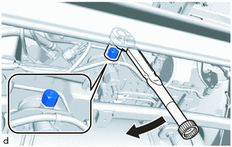
INSTALL REAR AXLE BEAM ASSEMBLY
-
INSTALL NO. 2 FC EXHAUST PIPE
-
INSTALL NO. 3 FC EXHAUST PIPE
-
INSTALL FC EXHAUST TAIL PIPE ASSEMBLY
-
SECOND LEAK CHECK
Note
-
Secondary leak inspection is performed after primary leak inspection has found no leaks, and filling with compressed hydrogen gas has been performed.
-
When performing secondary leak inspection, the vehicle cannot be driven to the hydrogen station under its own power, so transport it using a car carrier, etc.
-
At the hydrogen station, fill the tanks completely with compressed hydrogen gas.
-
Turn the power switch to on (READY), check that the READY indicator in the combination meter is illuminated, and then turn the power switch off.
Tech Tips
This is done to apply hydrogen gas pressure to the hydrogen gas piping.
-
Blow compressed air around the underside of the vehicle.
Tech Tips
To enable accurate detection of hydrogen gas leaks from the piping, blow compressed air from the front of the vehicle towards the rear.
-
If there are water droplets, etc. adhering to any of the measurement locations, wipe them away before performing the procedures.
Note
If measurements are performed while water droplets, etc. are adhered, the hydrogen gas detector may be damaged.
-
Using SST and a hydrogen gas detector, measure each of the measurement locations for approximately 10 continuous seconds per location.
- SST
- 09401-62010
Note
-
Figure 3. <Hydrogen Gas Detector Contact Location and Direction>
*a Hydrogen Gas Detector *b Side View *c Cutaway View To perform the measurement, hold the tip of the hydrogen gas detector as shown in the illustration (*c), in contact with a single location from any one of the directions shown.
-
Hold the tip in light contact with the location so that the tip does not deform.
Tech Tips
-
Immediately after the measurement starts, the measured value may be unstable.
-
If the measured value is outside of the specification, remove the hydrogen tank unit from the vehicle and replace the leaking component with a new one, and perform primary and secondary leak inspection again.
Figure 4. <Measurement Locations>
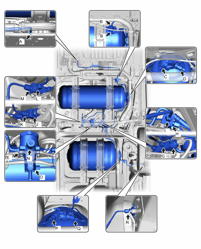
Measurement Location and Direction - - Illustration Item Measurement Location Measurement Method Specified Value A Connection between FC Stack Assembly and No. 1 Hydrogen Supply Tube Sub-assembly Measure the area near the piping, connecting portion, or sensor connecting portion. 300 ppm or less B Connection between No. 1 Hydrogen Supply Tube Sub-assembly and No. 2 Hydrogen Supply Tube Sub-assembly C Connection between No. 1 Hydrogen Tank Assembly and No. 4 Hydrogen Tank Tube D Connection between No. 1 Hydrogen Tank Assembly and No. 2 Hydrogen Tank Tube E Connection between Hydrogen Supply Regulator Assembly and No. 2 Hydrogen Supply Tube Sub-assembly F Hydrogen Tank Tube Joint (for Inlet Side), installation location of Hydrogen Tank Pressure Sensor G Connection between Hydrogen Tank Tube Joint (for Inlet Side) and No. 3 Hydrogen Tank Tube H Connection between Hydrogen Tank Tube Joint (for Inlet Side) and Hydrogen Tank Tube Assembly I Connection between Hydrogen Tank Tube Joint (for Inlet Side) and No. 2 Hydrogen Tank Tube J Hydrogen Tank Tube Joint (for Outlet Side), installation location of Hydrogen Tank Pressure Sensor K Connection between Hydrogen Tank Tube Joint (for Outlet Side) and No. 5 Hydrogen Tank Tube L Connection between Hydrogen Tank Tube Joint (for Outlet Side) and No. 4 Hydrogen Tank Tube M Connection between Hydrogen Tank Tube Joint (for Outlet Side) and No. 6 Hydrogen Tank Tube N Medium Pressure Port of Hydrogen Supply Regulator Assembly
*1
O Connection between Hydrogen Supply Regulator Assembly and No. 6 Hydrogen Tank Tube P Connection between No. 2 Hydrogen Tank Assembly and No. 5 Hydrogen Tank Tube Q Connection between No. 2 Hydrogen Tank Assembly and No. 3 Hydrogen Tank Tube R Connection between Hydrogen Inlet Receptacle Assembly and Hydrogen Tank Tube Assembly
*2
-
*1: If the value is not as specified, replace the O-ring of the medium pressure port.
-
*2: With the rear wheel house liner LH removed, perform measurement from the underside of the vehicle.
-
-
INSTALL REAR WHEEL HOUSE LINER LH
-
INSTALL REAR BUMPER SIDE SEAL LH
-
INSTALL REAR WHEEL HOUSE FRONT PLATE LH
-
INSTALL NO. 1 FLOOR UNDER COVER
-
INSTALL NO. 2 FLOOR UNDER COVER
-
INSTALL FRONT FLOOR CENTER COVER RH
-
INSTALL FRONT FLOOR CENTER COVER LH
-
INSTALL FRONT FLOOR COVER RH
-
INSTALL FRONT FLOOR COVER LH
-
INSTALL NO. 2 MOTOR UNDER COVER