FC BOOST CONTROL SYSTEM, Diagnostic DTC:P1D0E-450
| DTC Code | DTC Name |
|---|---|
| P1D0E-450 | FVH (FC Converter Output Voltage)/VH Voltage Correlation |
DESCRIPTION
The FC boost control ECU detects high voltage after boosting (FVH) using the voltage sensor which is located inside the FC converter assembly. In addition, the motor generator control ECU (MG ECU) detects high voltage after boosting (VH) using the inverter voltage sensor which is located inside the inverter.
| DTC No. | Detection Item | DTC Detection Condition | Trouble Area | Warning Indicate |
|---|---|---|---|---|
| P1D0E-450 | FVH (FC Converter Output Voltage)/VH Voltage Correlation | The difference between the inverter voltage after boosting (VH) and the FC converter output (1 trip detection logic) |
|
Master Warning Light: Comes on |
| DTC No. | System | Data List |
|---|---|---|
| P1D0E-450 | FCDC | FC Converter Output Voltage |
| EV | VH-Voltage after Boosting |
CAUTION / NOTICE / HINT
CAUTION:
-


Before the following operations are conducted, take precautions to prevent electric shock by turning the power switch off, wearing insulated gloves, and removing the service plug grips from both FC stack assembly and EV battery.
-
Inspecting the high-voltage system
-
Disconnecting the low voltage connector of the inverter with converter assembly
-
Disconnecting the low voltage connector of the EV battery
-
Disconnecting the low voltage connector of the FC stack assembly
-
Disconnecting the low voltage connector of the FC converter assembly
Tech Tips
No removal order is specified for the service plug grips of the FC stack assembly and EV battery.
-

After removing the service plug grip from the EV battery, put it in your pocket to prevent other technicians from accidentally reconnecting it while you are working on the high-voltage system. After removing the service grip from the FC stack assembly, store it in a safe location and use the "HIGH-VOLTAGE, DO NOT TOUCH" sign to notify other technicians that you are working on the high-voltage system.
-

*a Without waiting for 10 minutes After removal of the service plug grips of both FC stack assembly and EV battery, wait for at least 10 minutes before touching the high-voltage connectors and terminals. After waiting for 10 minutes, check the voltage at the terminals in the inspection point in the inverter with converter assembly. The voltage should be 0 V before beginning work.
Tech Tips
At least 10 minutes are necessary to discharge the high-voltage capacitors inside the inverter with converter assembly and FC stack assembly.
Note
-
When reinstalling the service plug grip to the FC stack assembly or the EV battery, slide the lever of the service plug until the letters "UNLOCK" are completely hidden, and insert it firmly.
-
When the vehicle is parked with the power switch off, if the FC control ECU judges that the FC stack temperature will go below 0°C (32°F), it activates the FC air compressor, hydrogen pump and FC cooling water pump for a maximum of 180 seconds and drains water from the FC stack assembly. When performing inspection or repairs with the power switch off (not on (IG) or on (READY)), disconnect the cable from the negative (-) auxiliary battery terminal before performing work (If the auxiliary battery voltage is needed to conduct inspection, warm up the FC system beforehand).
-
After turning the power switch off, waiting time may be required before disconnecting the cable from the negative (-) auxiliary battery terminal. Therefore, make sure to read the disconnecting the cable from the negative (-) auxiliary battery terminal notices before proceeding with work.
Tech Tips
After the repair, clear the DTCs and perform the following procedure to check that DTCs are not output.
-
Turn the power switch on (READY) and wait for 5 seconds or more.
PROCEDURE
-
CHECK DTC OUTPUT (FCDC)
-
Connect the GTS to the DLC3.
-
Turn the power switch on (IG).
-
Turn the GTS on.
-
Enter the following menus: Powertrain / FCDC / Trouble Codes.
Powertrain > FCDC > Trouble Codes -
Check for DTCs.
Result Result Proceed to "DTC P1D0E-450 only is output" or "DTCs except the ones in the table below are also output" A Any of the following DTCs are also output B Malfunction Content Relevant DTC Sensor and actuator circuit malfunction P1D1E-450 FC Converter Output Voltage Sensor Circuit Low P1D1F-450 FC Converter Output Voltage Sensor Circuit High Tech Tips
DTC P1D0E-450 may be output as a result of the malfunction indicated by the DTCs above.
-
Turn the power switch off.
B 
GO TO DTC CHART (FC BOOST CONTROL SYSTEM) Click here
A 
-
-
CHECK DTC OUTPUT (EV)
-
Connect the GTS to the DLC3.
-
Turn the power switch on (IG).
-
Turn the GTS on.
-
Enter the following menus: Powertrain / EV / Trouble Codes.
Powertrain > EV > Trouble Codes -
Check for DTCs.
Result Result Proceed to "EV related DTCs are not output" or "DTCs except the ones in the table below are output" A Any of the following DTCs are output B Malfunction Content Relevant DTC Sensor and actuator circuit malfunction P0A78-586 Drive Motor "A" Inverter Performance P0A94-442 Boosting Converter Performance System malfunction P0A78-266, 267 Drive Motor "A" Inverter Performance P0C76-523 EV Battery System Discharge Time Too Long Tech Tips
-
DTC P1D0E-450 may be output as a result of the malfunction indicated by the DTCs above.
-
The chart above is listed in inspection order of priority.
-
Check DTCs that are output at the same time by following the listed order. (The main cause of the malfunction can be determined without performing unnecessary inspections.)
-
-
Turn the power switch off.
B
GO TO DTC CHART (HYBRID CONTROL SYSTEM) Click here
A
-
-
CLEAR DTC
-
Connect the GTS to the DLC3.
-
Turn the power switch on (IG).
-
Turn the GTS on.
-
Enter the following menus: Powertrain / FCDC / Trouble Codes.
Powertrain > FCDC > Clear DTCs -
Enter the following menus: Powertrain / EV / Trouble Codes.
Powertrain > EV > Clear DTCs -
Clear the DTCs.
Result Proceed to NEXT -
Turn the power switch off and wait for 3 minutes or more.
NEXT
-
-
CHECK DTC OUTPUT (FCDC)
-
Connect the GTS to the DLC3.
-
Turn the power switch on (IG).
-
Turn the GTS on.
-
Enter the following menus: Powertrain / FCDC / Trouble Codes.
Powertrain > FCDC > Trouble Codes -
Check for DTCs.
Result Result Proceed to "DTCs are not output" or "DTCs except the ones in the table below are output" A Any of the following DTCs are output B Malfunction Content Relevant DTC Sensor and actuator circuit malfunction P1D1E-450 FC Converter Output Voltage Sensor Circuit Low P1D1F-450 FC Converter Output Voltage Sensor Circuit High Tech Tips
DTC P1D0E-450 may be output as a result of the malfunction indicated by the DTCs above.
-
Turn the power switch off.
B
GO TO DTC CHART (FC BOOST CONTROL SYSTEM) Click here
A
-
-
CHECK DTC OUTPUT (EV)
-
Connect the GTS to the DLC3.
-
Turn the power switch on (IG).
-
Turn the GTS on.
-
Enter the following menus: Powertrain / EV / Trouble Codes.
Powertrain > EV > Trouble Codes -
Check for DTCs.
Result Result Proceed to "EV related DTCs are not output" or "DTCs except the ones in the table below are output" A Any of the following DTCs are output B Malfunction Content Relevant DTC Sensor and actuator circuit malfunction P0A78-586 Drive Motor "A" Inverter Performance P0A94-442 Boosting Converter Performance System malfunction P0A78-266, 267 Drive Motor "A" Inverter Performance P0C76-523 EV Battery System Discharge Time Too Long Tech Tips
-
DTC P1D0E-450 may be output as a result of the malfunction indicated by the DTCs above.
-
The chart above is listed in inspection order of priority.
-
Check DTCs that are output at the same time by following the listed order. (The main cause of the malfunction can be determined without performing unnecessary inspections.)
-
-
Turn the power switch off.
B
GO TO DTC CHART (HYBRID CONTROL SYSTEM) Click here
A
-
-
SIMULATION TEST (FCDC)
-
Turn the power switch on (READY).
-
Drive the vehicle in a city area under the vehicle and driving conditions based on the recorded freeze frame data for approximately 10 minutes.
CAUTION:
When performing the confirmation driving pattern, obey all speed limits and traffic laws.
-
Connect the GTS to the DLC3.
-
Turn the power switch on (IG).
-
Turn the GTS on.
-
Enter the following menus: Powertrain / FCDC / Trouble Codes.
Powertrain > FCDC > Trouble Codes -
Check for DTCs.
Result Result Proceed to "DTCs are not output" or "DTCs except the ones in the table below are output" A Any of the following DTCs are output B Malfunction Content Relevant DTC Sensor and actuator circuit malfunction P1D1E-450 FC Converter Output Voltage Sensor Circuit Low P1D1F-450 FC Converter Output Voltage Sensor Circuit High Tech Tips
DTC P1D0E-450 may be output as a result of the malfunction indicated by the DTCs above.
-
Turn the power switch off.
B
GO TO DTC CHART (FC BOOST CONTROL SYSTEM) Click here
A
-
-
SIMULATION TEST (EV)
-
Connect the GTS to the DLC3.
-
Turn the power switch on (IG).
-
Turn the GTS on.
-
Enter the following menus: Powertrain / EV / Trouble Codes.
Powertrain > EV > Trouble Codes -
Check for DTCs.
Result Result Proceed to "EV related DTCs are not output" or "DTCs except the ones in the table below are output" A Any of the following DTCs are output B Malfunction Content Relevant DTC Sensor and actuator circuit malfunction P0A78-586 Drive Motor "A" Inverter Performance P0A94-442 Boosting Converter Performance System malfunction P0A78-266, 267 Drive Motor "A" Inverter Performance P0C76-523 EV Battery System Discharge Time Too Long Tech Tips
-
DTC P1D0E-450 may be output as a result of the malfunction indicated by the DTCs above.
-
The chart above is listed in inspection order of priority.
-
Check DTCs that are output at the same time by following the listed order. (The main cause of the malfunction can be determined without performing unnecessary inspections.)
-
-
Turn the power switch off.
B
GO TO DTC CHART (HYBRID CONTROL SYSTEM) Click here
A
-
-
CHECK CONNECTOR CONNECTION CONDITION (INVERTER WITH CONVERTER ASSEMBLY CONNECTOR)
Result Result Proceed to OK A NG (The connector is not connected securely) B NG (The terminals are not making secure contact or are deformed, or water or foreign matter exists in the connector) C CAUTION:
Be sure to wear insulated gloves.
-
Check that the service plug grip is not installed to FC stack assembly and EV battery.
Note
After removing the service plug grip, do not turn the power switch on (READY), unless instructed by the repair manual because this may cause a malfunction.
-
Check the connection condition of the low voltage connector of the inverter with converter assembly and the contact pressure of each terminal. Check the terminals for deformation, and check the connector for water ingress and foreign matter.
Note
Before disconnecting the connector, confirm that it is properly connected by checking that the locking claws are engaged and that the connector does not pull out.
OK - The connector is connected securely. - The terminals are not deformed and are connected securely. - No water or foreign matter in the connector. Result Result Proceed to OK A NG (The connector is not connected securely.) B NG (The terminals are not making secure contact or are deformed, or water or foreign matter exists in the connector.) C
B
CONNECT SECURELY
C
REPAIR OR REPLACE HARNESS OR CONNECTOR
A
-
-
CHECK INVERTER WITH CONVERTER ASSEMBLY (FC CONVERTER POWER OUTLET CABLE CONNECTION CONDITION)
CAUTION:
Be sure to wear insulated gloves.
-
Check that the service plug grip is not installed to FC stack assembly and EV battery.
Note
After removing the service plug grip, do not turn the power switch on (READY), unless instructed by the repair manual because this may cause a malfunction.
-
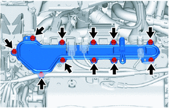
Remove the inverter terminal cover from the inverter with converter assembly.
Tech Tips
Make sure that no foreign matter, coolant or water has entered the inverter assembly with converter.
Confirm that the inverter coolant volume has not increased.
-
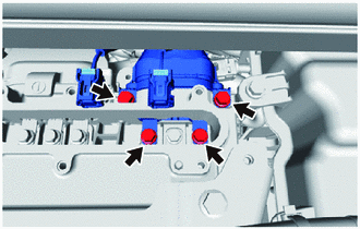
Check that the bolts for the FC converter power outlet cable are tightened to the specified torque, the FC converter power outlet cable is connected securely, and there are no contact problems.
Specified Condition T = 8.0 N*m (82 kgf*cm, 71 in.*lbf) -
Disconnect the FC converter power outlet cable from the inverter with converter assembly.
-
Check for arc marks at the terminals for the FC converter power outlet cable.
Result Result Proceed to The terminals are connected securely and there are no contact problems There are no arc marks A The terminals are not connected securely and there is a contact problem There are arc marks B The terminals are connected securely and there are no contact problems There are arc marks The terminals are not connected securely and there is a contact problem There are no arc marks C -
Reconnect the FC converter power outlet cable to the inverter with converter assembly.
-
Install the inverter terminal cover to the inverter with converter assembly.
B
REPLACE MALFUNCTIONING PARTS
C
CONNECT SECURELY
A
-
-
CHECK FC CONVERTER ASSEMBLY (FC CONVERTER POWER OUTLET CABLE CONNECTION CONDITION)
CAUTION:
Be sure to wear insulated gloves.
-
Check that the service plug grip is not installed to FC stack assembly and EV battery.
Note
After removing the service plug grip, do not turn the power switch on (READY), unless instructed by the repair manual because this may cause a malfunction.
-
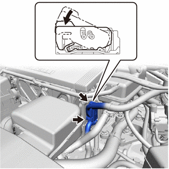
Remove the front FC converter service hole cover from the FC converter assembly.
-
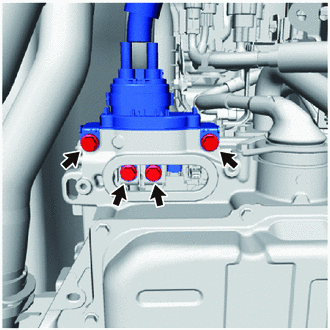
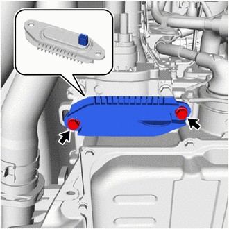
Check that the bolts for the FC converter power outlet cable are tightened to the specified torque, the FC converter power outlet cable is connected securely, and there are no contact problems.
Specified Condition T = 8.0 N*m (82 kgf*cm, 71 in.*lbf) -
Disconnect the FC converter power outlet cable from the FC converter assembly.
-
Check for arc marks at the terminals for the FC converter power outlet cable.
Result Result Proceed to The terminals are connected securely and there are no contact problems There are no arc marks A The terminals are not connected securely and there is a contact problem There are arc marks B The terminals are connected securely and there are no contact problems There are arc marks The terminals are not connected securely and there is a contact problem There are no arc marks C -
Reconnect the FC converter power outlet cable to the FC converter assembly.
-
Install the front FC converter service hole cover to the FC converter assembly.
B
REPLACE MALFUNCTIONING PARTS
C
CONNECT SECURELY
A
-
-
INSPECT FC CONVERTER POWER OUTLET CABLE
CAUTION:
Be sure to wear insulated gloves.
-
Check that the service plug grip is not installed to FC stack assembly and EV battery.
Note
After removing the service plug grip, do not turn the power switch on (READY), unless instructed by the repair manual because this may cause a malfunction.
-
Remove the inverter terminal cover from the inverter with converter assembly.
-
Disconnect the FC converter power outlet cable from the inverter with converter assembly.
-
Remove the front FC converter service hole cover from the FC converter assembly.
-
Disconnect the FC converter power outlet cable from the FC converter assembly.
-
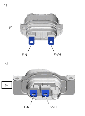
*1 FC Converter Power Outlet Cable
(Inverter with Converter Assembly Side Connector)
*2 FC Converter Power Outlet Cable
(FC Converter Assembly Side Connector)
Measure the resistance according to the value(s) in the table below.
Standard Resistance Tester Connection Switch Condition Specified Condition p1-1 (F-N) - p2-1 (F-N) Power switch off Below 1 Ω p1-2 (F-VH) - p2-2 (F-VH) Power switch off Below 1 Ω Result Proceed to OK NG -
Reconnect the FC converter power outlet cable.
-
Install the front FC converter service hole cover to the FC converter assembly.
-
Install the inverter terminal cover to the inverter with converter assembly.
NG
REPLACE FC CONVERTER POWER OUTLET CABLE Click here
OK
-
-
READ VALUE USING GTS
-
Turn the power switch off and wait for 10 minutes or more.
Tech Tips
Waiting for at least 10 minutes is required to discharge the inverter with converter assembly and FC converter assembly to 0 V.
-
Connect the GTS to the DLC3.
-
Turn the power switch on (IG).
-
Turn the GTS on.
-
Enter the following menus: Powertrain / FCDC / Data List / FC Converter Output Voltage
Powertrain > FCDC > Data ListTester Display FC Converter Output Voltage -
Enter the following menus: Powertrain / EV / Data List / VH-Voltage after Boosting
Powertrain > EV > Data ListTester Display VH-Voltage after Boosting -
Read the Data List.
Result GTS Display Proceed to FC Converter Output Voltage VH-Voltage after Boosting Less than 10 V Less than 10 V A 10 V or higher B 10 V or higher Less than 10 V C 10 V or higher D Tech Tips
Data List (FCDC) and Data List (EV) can be checked simultaneously using the Data List functions of the GTS.
-
Turn the power switch off.
B
REPLACE INVERTER WITH CONVERTER ASSEMBLY Click here
C
REPLACE FC CONVERTER ASSEMBLY Click here
D 
REPLACE FC CONVERTER ASSEMBLY Click here
A
-
-
CLEAR DTC
-
Connect the GTS to the DLC3.
-
Turn the power switch on (IG).
-
Turn the GTS on.
-
Enter the following menus: Powertrain / FCDC / Trouble Codes.
Powertrain > FCDC > Clear DTCs -
Clear the DTCs.
Result Proceed to NEXT -
Turn the power switch off and wait for 3 minutes or more.
NEXT
-
-
CHECK DTC OUTPUT (FCDC)
-
Connect the GTS to the DLC3.
-
Turn the power switch on (READY) and wait for 5 seconds or more.
-
Turn the GTS on.
-
Enter the following menus: Powertrain / FCDC / Trouble Codes.
Powertrain > FCDC > Trouble Codes -
Check for DTCs.
OK DTC is not output. Result Proceed to NEXT -
Turn the power switch off.
NEXT
CHECK FOR INTERMITTENT PROBLEMS Click here
-
-
REPLACE FC CONVERTER ASSEMBLY
Result Proceed to NEXT
NEXT
REPLACE INVERTER WITH CONVERTER ASSEMBLY Click here