FC BOOST CONTROL SYSTEM, Diagnostic DTC:P2511-450
| DTC Code | DTC Name |
|---|---|
| P2511-450 | FCDC CPU Circuit Intermittent No Continuity |
DESCRIPTION
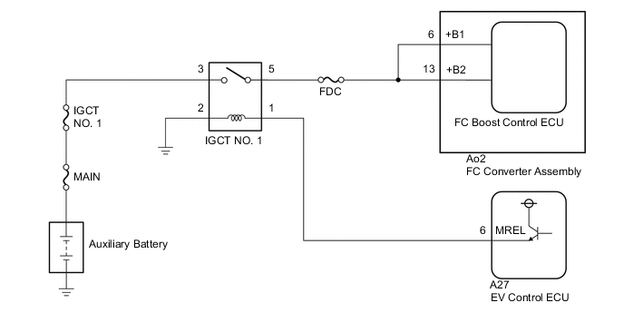
The FC boost control ECU is located inside the FC converter assembly. It monitors the +B power source voltage and detects a momentary interruption.
| DTC No. | Detection Item | DTC Detection Condition | Trouble Area | Warning Indicate |
|---|---|---|---|---|
| P2511-450 | FCDC CPU Circuit Intermittent No Continuity | The FC boost control ECU was reset due to a momentary interruption of the power supply while the power switch is on (READY). (1 trip detection logic) |
|
Master Warning Light: Comes on |
WIRING DIAGRAM
CAUTION / NOTICE / HINT
CAUTION:
-


Before the following operations are conducted, take precautions to prevent electric shock by turning the power switch off, wearing insulated gloves, and removing the service plug grips from both FC stack assembly and EV battery.
-
Inspecting the high-voltage system
-
Disconnecting the low voltage connector of the inverter with converter assembly
-
Disconnecting the low voltage connector of the EV battery
-
Disconnecting the low voltage connector of the FC stack assembly
-
Disconnecting the low voltage connector of the FC converter assembly
Tech Tips
No removal order is specified for the service plug grips of the FC stack assembly and EV battery.
-

After removing the service plug grip from the EV battery, put it in your pocket to prevent other technicians from accidentally reconnecting it while you are working on the high-voltage system. After removing the service grip from the FC stack assembly, store it in a safe location and use the "HIGH-VOLTAGE, DO NOT TOUCH" sign to notify other technicians that you are working on the high-voltage system.
-

*a Without waiting for 10 minutes After removal of the service plug grips of both FC stack assembly and EV battery, wait for at least 10 minutes before touching the high-voltage connectors and terminals. After waiting for 10 minutes, check the voltage at the terminals in the inspection point in the inverter with converter assembly. The voltage should be 0 V before beginning work.
Tech Tips
At least 10 minutes are necessary to discharge the high-voltage capacitors inside the inverter with converter assembly and FC stack assembly.
Note
-
When reinstalling the service plug grip to the FC stack assembly or the EV battery, slide the lever of the service plug until the letters "UNLOCK" are completely hidden, and insert it firmly.
-
When the vehicle is parked with the power switch off, if the FC control ECU judges that the FC stack temperature will go below 0°C (32°F), it activates the FC air compressor, hydrogen pump and FC cooling water pump for a maximum of 180 seconds and drains water from the FC stack assembly. When performing inspection or repairs with the power switch off (not on (IG) or on (READY)), disconnect the cable from the negative (-) auxiliary battery terminal before performing work (If the auxiliary battery voltage is needed to conduct inspection, warm up the FC system beforehand).
-
After turning the power switch off, waiting time may be required before disconnecting the cable from the negative (-) auxiliary battery terminal. Therefore, make sure to read the disconnecting the cable from the negative (-) auxiliary battery terminal notices before proceeding with work.
Tech Tips
After the repair, clear the DTCs and perform the following procedure to check that DTCs are not output.
-
Turn the power switch on (READY) and wait for 30 seconds or more.
PROCEDURE
-
CHECK AUXILIARY BATTERY TERMINAL
-
Confirm whether the auxiliary battery terminals have been disconnected recently.
Result Result Proceed to Terminals have been disconnected A Terminals have not been disconnected B
B 
GO TO STEP 5 Click here
A 
-
-
CHECK WARNING LIGHT (MASTER WARNING LIGHT)
-
With the power switch off, turn the power switch on (READY) and wait for 30 seconds or more.
-
Confirm that the master warning light illuminates.
Result Result Proceed to Master warning light illuminates A Master warning light does not illuminates B Tech Tips
DTC P2511-450 may be stored after disconnecting and reconnecting the auxiliary battery terminals. If this happens, the DTC will not be output if the power switch is turned off and then on (READY) again. In this case, clear DTCs to complete the inspection.
-
Turn the power switch off.
B 
END
A
-
-
CLEAR DTC
-
Connect the GTS to the DLC3.
-
Turn the power switch on (IG).
-
Turn the GTS on.
-
Enter the following menus: Powertrain / FCDC / Trouble Codes.
Powertrain > FCDC > Clear DTCs -
Clear the DTCs.
Result Proceed to NEXT -
Turn the power switch off and wait for 3 minutes or more.
NEXT
-
-
CHECK DTC OUTPUT (FCDC)
-
Connect the GTS to the DLC3.
-
Turn the power switch on (READY) and wait for 30 seconds or more.
-
Turn the GTS on.
-
Enter the following menus: Powertrain / FCDC / Trouble Codes.
Powertrain > FCDC > Trouble Codes -
Check for DTCs.
Result Result Proceed to DTC P2511-149 is output again A DTCs other than DTC P2511-149 are also output B -
Turn the power switch off.
B
GO TO DTC CHART (FC BOOST CONTROL SYSTEM) Click here
A
-
-
CHECK AUXILIARY BATTERY TERMINAL (CONTACT PROBLEM)
-
Check the connection of the auxiliary battery terminal.
OK The terminal is connected securely and there is no contact problem. Result Proceed to OK NG
NG
CONNECT SECURELY
OK
-
-
CHECK CONNECTOR CONNECTION CONDITION (FC CONVERTER ASSEMBLY CONNECTOR)
Result Result Proceed to OK A NG (The connector is not connected securely) B NG (The terminals are not making secure contact or are deformed, or water or foreign matter exists in the connector) C CAUTION:
Be sure to wear insulated gloves.
-
Check that the service plug grip is not installed to FC stack assembly and EV battery.
Note
After removing the service plug grip, do not turn the power switch on (READY), unless instructed by the repair manual because this may cause a malfunction.
-
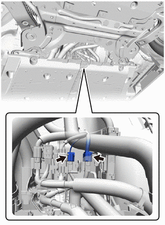
Check the connection condition of the FC converter assembly connector and the contact pressure of each terminal. Check the terminals for deformation, and check the connector for water ingress and foreign matter.
Note
Before disconnecting the connector, confirm that it is properly connected by checking that the locking claws are engaged and that the connector does not pull out.
OK - The connector is connected securely. - The terminals are not deformed and are connected securely. - No water or foreign matter in the connector. Result Result Proceed to OK A NG (The connector is not connected securely) B NG (The terminals are not making secure contact or are deformed, or water or foreign matter exists in the connector) C
B
CONNECT SECURELY
C
REPAIR OR REPLACE HARNESS OR CONNECTOR
A
-
-
INSPECT RELAY (IGCT NO.1 RELAY)
Result Proceed to OK NG
NG
REPLACE RELAY (IGCT NO.1 RELAY)
OK
-
CHECK HARNESS AND CONNECTOR (FC CONVERTER ASSEMBLY - IGCT NO. 1 RELAY)
CAUTION:
Be sure to wear insulated gloves.
-
Check that the service plug grip is not installed to FC stack assembly and EV battery.
Note
After removing the service plug grip, do not turn the power switch on (READY), unless instructed by the repair manual because this may cause a malfunction.
-
Remove the IGCT NO. 1 relay from the motor compartment relay block.
-
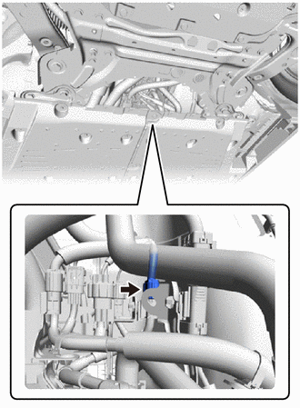
Disconnect the Ao2 FC converter assembly connector.
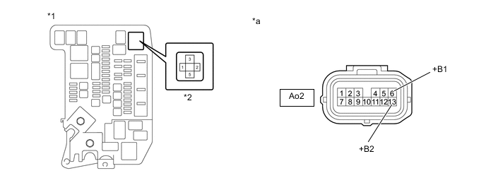
*1 Motor compartment relay block *2 IGCT NO. 1 Relay *a Front view of wire harness connector
(to FC Converter Assembly)
- - -
Measure the resistance according to the value(s) in the table below.
Standard Resistance Tester Connection Switch Condition Specified Condition Ao2-6 (+B1) - 5 (IGCT NO. 1 relay holder) Power switch off Below 1 Ω Ao2-13 (+B2) - 5 (IGCT NO. 1 relay holder) Power switch off Below 1 Ω -
Install the IGCT NO. 1 relay.
-
Connect the FC converter assembly connector.
Result Proceed to OK NG
OK
REPLACE FC CONVERTER ASSEMBLY Click here
NG
REPAIR OR REPLACE HARNESS OR CONNECTOR
-