FC BOOST CONTROL SYSTEM, Diagnostic DTC:P1DDA-450, P1DDB-450, P1DDC-450, P1DDD-450
| DTC Code | DTC Name |
|---|---|
| P1DDA-450 | U Phase Reactor Current Degradation |
| P1DDB-450 | V Phase Reactor Current Degradation |
| P1DDC-450 | W Phase Reactor Current Degradation |
| P1DDD-450 | X Phase Reactor Current Degradation |
DESCRIPTION
Output values of any phase reactor current sensors, located inside the FC converter assembly, is smaller than the lower limit of the electric current value estimated from the FC voltage.
| DTC No. | Detection Item | DTC Detection Condition | Trouble Area | Warning Indicate |
|---|---|---|---|---|
| P1DDA-450 | U Phase Reactor Current Degradation | Electric current value detected by the FC converter current sensor (U phase reactor current sensor) is smaller than the lower limit of the electric current value estimated from the FC voltage and the gate signal. (1 trip detection logic) |
|
Master Warning Light: Comes on |
| P1DDB-450 | V Phase Reactor Current Degradation | Electric current value detected by the FC converter current sensor (V phase reactor current sensor) is smaller than the lower limit of the electric current value estimated from the FC voltage and the gate signal. (1 trip detection logic) |
|
Master Warning Light: Comes on |
| P1DDC-450 | W Phase Reactor Current Degradation | Electric current value detected by the FC converter current sensor (W phase reactor current sensor) is smaller than the lower limit of the electric current value estimated from the FC voltage and the gate signal. (1 trip detection logic) |
|
Master Warning Light: Comes on |
| P1DDD-450 | X Phase Reactor Current Degradation | Electric current value detected by the FC converter current sensor (X phase reactor current sensor) is smaller than the lower limit of the electric current value estimated from the FC voltage and the gate signal. (1 trip detection logic) |
|
Master Warning Light: Comes on |
| DTC No. | Data List |
|---|---|
| P1DDA-450 |
|
| P1DDB-450 |
|
| P1DDC-450 |
|
| P1DDD-450 |
|
WIRING DIAGRAM
Refer to the wiring diagram for the high-voltage circuit.
Refer to the wiring diagram for the FC relay circuit.
CAUTION / NOTICE / HINT
CAUTION:
-


Before the following operations are conducted, take precautions to prevent electric shock by turning the power switch off, wearing insulated gloves, and removing the service plug grips from both FC stack assembly and EV battery.
-
Inspecting the high-voltage system
-
Disconnecting the low voltage connector of the inverter with converter assembly
-
Disconnecting the low voltage connector of the EV battery
-
Disconnecting the low voltage connector of the FC stack assembly
-
Disconnecting the low voltage connector of the FC converter assembly
Tech Tips
No removal order is specified for the service plug grips of the FC stack assembly and EV battery.
-

After removing the service plug grip from the EV battery, put it in your pocket to prevent other technicians from accidentally reconnecting it while you are working on the high-voltage system. After removing the service grip from the FC stack assembly, store it in a safe location and use the "HIGH-VOLTAGE, DO NOT TOUCH" sign to notify other technicians that you are working on the high-voltage system.
-

*a Without waiting for 10 minutes After removal of the service plug grips of both FC stack assembly and EV battery, wait for at least 10 minutes before touching the high-voltage connectors and terminals. After waiting for 10 minutes, check the voltage at the terminals in the inspection point in the inverter with converter assembly. The voltage should be 0 V before beginning work.
Tech Tips
At least 10 minutes are necessary to discharge the high-voltage capacitors inside the inverter with converter assembly and FC stack assembly.
Note
-
When reinstalling the service plug grip to the FC stack assembly or the EV battery, slide the lever of the service plug until the letters "UNLOCK" are completely hidden, and insert it firmly.
-
When the vehicle is parked with the power switch off, if the FC control ECU judges that the FC stack temperature will go below 0°C (32°F), it activates the FC air compressor, hydrogen pump and FC cooling water pump for a maximum of 180 seconds and drains water from the FC stack assembly. When performing inspection or repairs with the power switch off (not on (IG) or on (READY)), disconnect the cable from the negative (-) auxiliary battery terminal before performing work (If the auxiliary battery voltage is needed to conduct inspection, warm up the FC system beforehand).
-
After turning the power switch off, waiting time may be required before disconnecting the cable from the negative (-) auxiliary battery terminal. Therefore, make sure to read the disconnecting the cable from the negative (-) auxiliary battery terminal notices before proceeding with work.
Tech Tips
After the repair, clear the DTCs and perform the following procedure to check that DTCs are not output.
-
Turn the power switch on (IG).
-
Enter the following menus: Powertrain / FC / Data List / FC Mode, FC Intermittent Operation.
-
Move the shift lever to P, turn the power switch on (READY) and wait until the FC system is activated (Waiting for at least 2 minutes is required after turning the power switch on).
-
FC system is activated: Data List shows that "FC Mode" is "FC Working" and "FC Intermittent Operation" is "OFF".
-
Wait at least 15 seconds with the FC system activated.
PROCEDURE
-
CHECK DTC OUTPUT (FCDC)
-
Connect the GTS to the DLC3.
-
Turn the power switch on (IG).
-
Turn the GTS on.
-
Enter the following menus: Powertrain / FCDC / Trouble Codes.
Powertrain > FCDC > Trouble Codes -
Check for DTCs.
Result Result Proceed to "DTC P1DDA-450, P1DDB-450, P1DDC-450 or P1DDD-450 only is output" or "DTCs except the ones in the table below are also output" A Any of the following DTCs are also output B Malfunction Content Relevant DTC Sensor and actuator circuit malfunction P1D31-450 U Phase Reactor Current Sensor Circuit (Offset) P1D32-450 U Phase Reactor Current Sensor Circuit Low P1D33-450 U Phase Reactor Current Sensor Circuit High P1D36-450 V Phase Reactor Current Sensor Circuit (Offset) P1D37-450 V Phase Reactor Current Sensor Circuit Low P1D38-450 V Phase Reactor Current Sensor Circuit High P1D3B-450 W Phase Reactor Current Sensor Circuit (Offset) P1D3C-450 W Phase Reactor Current Sensor Circuit Low P1D3D-450 W Phase Reactor Current Sensor Circuit High P1D41-450 X Phase Reactor Current Sensor Circuit (Offset) P1D42-450 X Phase Reactor Current Sensor Circuit Low P1D43-450 X Phase Reactor Current Sensor Circuit High P1DE0-450 U Phase Output Diode Circuit P1DE1-450 V Phase Output Diode Circuit P1DE2-450 W Phase Output Diode Circuit P1DE3-450 X Phase Output Diode Circuit System malfunction P1D0F-450 FVC (Cell Monitor Voltage)/FVL (FC Converter Input Voltage) Correlation P1D20-450 FVL (FC Converter Input Voltage) Low Voltage/Sensor Circuit Tech Tips
-
DTC P1DDA-450, P1DDB-450, P1DDC-450 or P1DDD-450 may be output as a result of the malfunction indicated by the DTCs above.
-
The chart above is listed in inspection order of priority.
-
Check DTCs that are output at the same time by following the listed order. (The main cause of the malfunction can be determined without performing unnecessary inspections.)
-
-
Turn the power switch off.
B 
GO TO DTC CHART (FC BOOST CONTROL SYSTEM) Click here
A 
-
-
CHECK DTC OUTPUT (EV)
-
Connect the GTS to the DLC3.
-
Turn the power switch on (IG).
-
Turn the GTS on.
-
Enter the following menus: Powertrain / EV / Trouble Codes.
Powertrain > EV > Trouble Codes -
Check for DTCs.
Result Result Proceed to EV related DTCs are not output A DTC P1D98-450 is output B Tech Tips
DTC P1DDA-450, P1DDB-450, P1DDC-450 or P1DDD-450 may be output as a result of the malfunction indicated by the DTCs above.
-
Turn the power switch off.
B
GO TO DTC CHART (HYBRID CONTROL SYSTEM) Click here
A
-
-
CLEAR DTC
-
Connect the GTS to the DLC3.
-
Turn the power switch on (IG).
-
Turn the GTS on.
-
Enter the following menus: Powertrain / FCDC / Trouble Codes.
Powertrain > FCDC > Clear DTCs -
Clear the DTCs.
Result Proceed to NEXT -
Turn the power switch off and wait for 3 minutes or more.
NEXT
-
-
CHECK DTC OUTPUT (FCDC)
-
Connect the GTS to the DLC3.
-
Turn the power switch on (IG).
-
Turn the GTS on.
-
Enter the following menus: Powertrain / FCDC / Trouble Codes.
Powertrain > FCDC > Trouble Codes -
Check for DTCs.
Result Result Proceed to DTCs are not output A Any of the following DTCs are output B Malfunction Content Relevant DTC Sensor and actuator circuit malfunction P1D31-450 U Phase Reactor Current Sensor Circuit (Offset) P1D32-450 U Phase Reactor Current Sensor Circuit Low P1D33-450 U Phase Reactor Current Sensor Circuit High P1D36-450 V Phase Reactor Current Sensor Circuit (Offset) P1D37-450 V Phase Reactor Current Sensor Circuit Low P1D38-450 V Phase Reactor Current Sensor Circuit High P1D3B-450 W Phase Reactor Current Sensor Circuit (Offset) P1D3C-450 W Phase Reactor Current Sensor Circuit Low P1D3D-450 W Phase Reactor Current Sensor Circuit High P1D41-450 X Phase Reactor Current Sensor Circuit (Offset) P1D42-450 X Phase Reactor Current Sensor Circuit Low P1D43-450 X Phase Reactor Current Sensor Circuit High P1DE0-450 U Phase Output Diode Circuit P1DE1-450 V Phase Output Diode Circuit P1DE2-450 W Phase Output Diode Circuit P1DE3-450 X Phase Output Diode Circuit System malfunction P1D0F-450 FVC (Cell Monitor Voltage)/FVL (FC Converter Input Voltage) Correlation P1D20-450 FVL (FC Converter Input Voltage) Low Voltage/Sensor Circuit Tech Tips
-
DTC P1DDA-450, P1DDB-450, P1DDC-450 or P1DDD-450 may be output as a result of the malfunction indicated by the DTCs above.
-
The chart above is listed in inspection order of priority.
-
Check DTCs that are output at the same time by following the listed order. (The main cause of the malfunction can be determined without performing unnecessary inspections.)
-
-
Turn the power switch off.
B
GO TO DTC CHART (FC BOOST CONTROL SYSTEM) Click here
A
-
-
SIMULATION TEST
-
Connect the GTS to the DLC3.
-
Turn the power switch on (READY). (A)
-
Turn the GTS on.
-
Enter the following menus: Powertrain / FCDC / Data List / FC Output Power
Powertrain > FCDC > Data ListTester Display FC Output Power -
Accelerate the vehicle to approximately 80 km/h (50 mph). (B)
-
While checking the Data List item "FC Output Power", depress the accelerator pedal and ensure that all conditions stated below are met. (C)
CAUTION:
When performing the confirmation driving pattern, obey all speed limits and traffic laws.
Driving condition Data List item "FC Output Power" value remains 65 kW or more for at least 2 seconds. 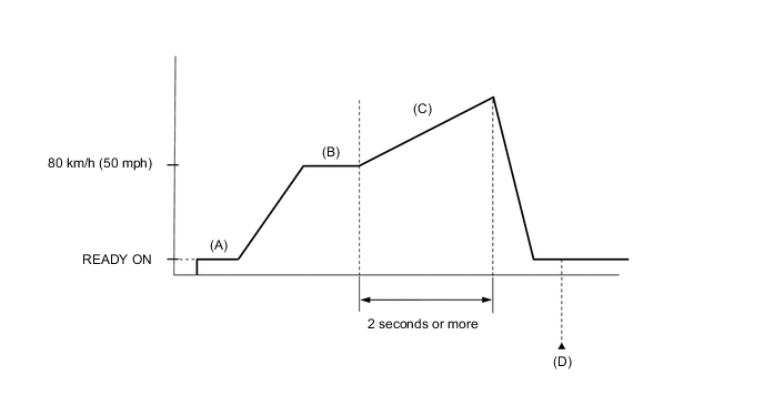
-
Enter the following menus: Powertrain / FCDC / Trouble Codes. (D)
Powertrain > FCDC > Trouble Codes -
Check for DTCs.
Result Result Proceed to "DTC P1DDA-450, P1DDB-450, P1DDC-450 or P1DDD-450 only is output" or "DTCs except the ones in the table below are also output" A DTCs are not output B Any of the following DTCs are output C Malfunction Content Relevant DTC Sensor and actuator circuit malfunction P1D31-450 U Phase Reactor Current Sensor Circuit (Offset) P1D32-450 U Phase Reactor Current Sensor Circuit Low P1D33-450 U Phase Reactor Current Sensor Circuit High P1D36-450 V Phase Reactor Current Sensor Circuit (Offset) P1D37-450 V Phase Reactor Current Sensor Circuit Low P1D38-450 V Phase Reactor Current Sensor Circuit High P1D3B-450 W Phase Reactor Current Sensor Circuit (Offset) P1D3C-450 W Phase Reactor Current Sensor Circuit Low P1D3D-450 W Phase Reactor Current Sensor Circuit High P1D41-450 X Phase Reactor Current Sensor Circuit (Offset) P1D42-450 X Phase Reactor Current Sensor Circuit Low P1D43-450 X Phase Reactor Current Sensor Circuit High P1DE0-450 U Phase Output Diode Circuit P1DE1-450 V Phase Output Diode Circuit P1DE2-450 W Phase Output Diode Circuit P1DE3-450 X Phase Output Diode Circuit System malfunction P1D0F-450 FVC (Cell Monitor Voltage)/FVL (FC Converter Input Voltage) Correlation P1D20-450 FVL (FC Converter Input Voltage) Low Voltage/Sensor Circuit Tech Tips
-
DTC P1DDA-450, P1DDB-450, P1DDC-450 or P1DDD-450 may be output as a result of the malfunction indicated by the DTCs above.
-
The chart above is listed in inspection order of priority.
-
Check DTCs that are output at the same time by following the listed order. (The main cause of the malfunction can be determined without performing unnecessary inspections.)
-
-
Turn the power switch off.
B
CHECK FOR INTERMITTENT PROBLEMS Click here
C
GO TO DTC CHART (FC BOOST CONTROL SYSTEM) Click here
A
-
-
PERFORM ACTIVE TEST USING GTS (FC STACK POSITIVE RELAY, FC STACK NEGATIVE RELAY)
-
Connect the GTS to the DLC3.
-
Turn the power switch on (IG).
-
Turn the GTS on.
-
Enter the following menus: Powertrain / EV / Active Test / FC Stack Positive Relay, FC Stack Negative Relay
Powertrain > EV > Active TestTester Display FC Stack Positive Relay
Powertrain > EV > Active TestTester Display FC Stack Negative Relay -
Check whether the FC relay operating sound occurs when performing the Active Test on the GTS.
OK FC relay operating sound occurs. Result Result Proceed to FC relay operating sound does not occur A FC relay operating sound occurs B -
Turn the power switch off.
B
REPLACE FC STACK ASSEMBLY Click here
A
-
-
REPLACE FC CONVERTER ASSEMBLY
Result Proceed to NEXT
NEXT
REPLACE FC STACK ASSEMBLY Click here