FC BOOST CONTROL SYSTEM PRECAUTION
-
PRECAUTIONS FOR INSPECTING EV CONTROL SYSTEM
-
Before the following operations are conducted, take precautions to prevent electric shock by turning the power switch off, wearing insulated gloves, and removing the service plug grips from both FC stack assembly and EV battery.
-
Inspecting the high-voltage system
-
Disconnecting the low voltage connector of the inverter with converter assembly
-
Disconnecting the low voltage connector of the EV battery
-
Disconnecting the low voltage connector of the FC stack assembly
-
Disconnecting the low voltage connector of the FC converter assembly
-
-
After removing the FC stack assembly and EV battery service plug grips, store them according to the following guidelines to prevent other technicians from accidentally reconnecting them while work is being performed on the high voltage systems.
-
The technician performing the work should put the EV battery service plug grip in their pocket and carry it with them.
-
Store the FC stack service plug grip with a "HIGH-VOLTAGE, DO NOT TOUCH" caution tag attached to it for other technicians.
Note
-
After turning the power switch off, waiting time may be required before disconnecting the cable from the negative (-) auxiliary battery terminal. Therefore, make sure to read the disconnecting the cable from the negative (-) auxiliary battery terminal notices before proceeding with work.
-
After removing the service plug grip, turning the power switch on (READY) may cause a malfunction. Do not turn the power switch on (READY) unless instructed by the repair manual.
Tech Tips
No removal order is specified for the service plug grips of the FC stack assembly and EV battery
-
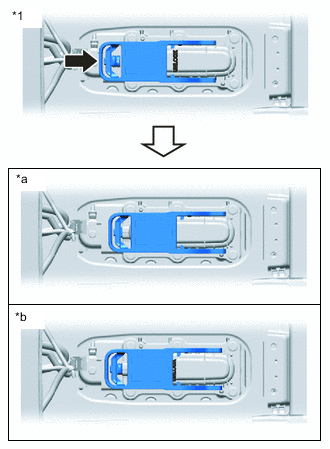
Remove the FC stack service plug grip.
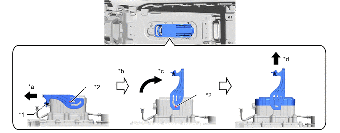
*1 Interlock Connector *2 Stopper *a Slide the lever of the FC stack service plug grip in the arrow direction until it stops at the stopper (slide the lever horizontally, as the interlock connector is provided). *b After the FC service plug grip stops, wait for at least 1 second before proceeding to perform the next step. *c Slowly turn the FC service plug grip lever until it stops at the stopper. *d Slowly pull the FC service plug grip lever upward to remove the service plug grip from the FC stack assembly. Note
-
Do not touch the terminal of the FC stack service plug grip.
-
Do not touch the rubber seal of the FC stack service plug grip.
-
In order to prevent foreign matter as well as moisture from entering, check that no foreign matter or moisture is present around the FC service plug grip. If found, clean the area up.
-
To prevent contamination by foreign matter or water droplets, cover the openings of the FC stack assembly with protective tape.
-
After removal, prevent the terminal of the FC service plug grip and the rubber seal from being contaminated.
-
-
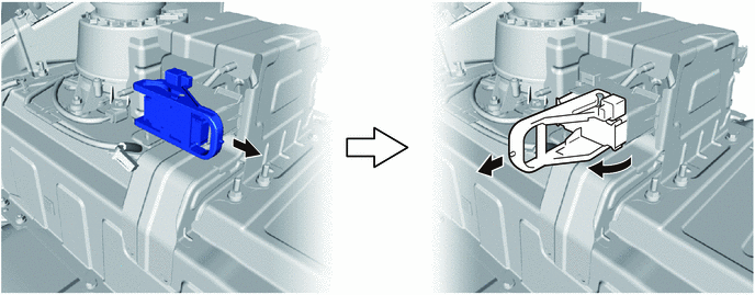
Remove the service plug grip (for EV).
-
-
After removing the service plug grip of both FC stack assembly and EV battery, wait for at least 10 minutes before touching any of the high-voltage connectors or terminals.
Tech Tips
Waiting for at least 10 minutes is required to discharge the high-voltage capacitor inside the inverter with converter assembly and FC converter assembly.
-
Check the voltage at the terminals in the inspection point in the inverter with converter assembly.
CAUTION:
Be sure to wear insulated gloves.
-
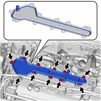
Remove the inverter cover from the inverter with converter assembly.
Note
-
Make sure to pull the connector cover assembly straight up, as a connector is connected to the bottom of the cover.
-
Do not allow any foreign matter or water to enter the inverter with converter assembly.
-
-
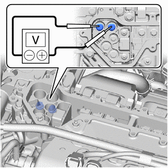
Measure the voltage according to the value(s) in the table below.
Tech Tips
Set the tester to DC750 V or more to measure the voltage.
-
-
When turning the power switch on (IG) during an inspection, do not press the power switch with the brake pedal depressed.
CAUTION:
Pressing the power switch with the brake pedal depressed causes the system to enter the READY ON state. This is very dangerous because high voltage may be applied to the inspection area.
-
Turn the power switch off, wear insulated gloves, and disconnect the cable from the negative (-) terminal of the auxiliary battery before touching any of the orange-colored wires of the high-voltage system.
Note
After turning the power switch off, waiting time may be required before disconnecting the cable from the negative (-) auxiliary battery terminal. Therefore, make sure to read the disconnecting the cable from the negative (-) auxiliary battery terminal notices before proceeding with work.
-
Turn the power switch off before performing any resistance checks.
-
Turn the power switch off before disconnecting or reconnecting any connectors.
-
When performing work involving high-voltage wires, use either a tool wrapped with vinyl insulation tape or an insulated tool.
-
When high-voltage connectors are removed, wrap the connectors with insulation tape to prevent them from contacting foreign matter.
-
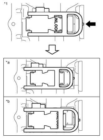
When reinstalling the service plug grips of the FC stack assembly and EV battery, slide the grip levers until "UNLOCK" is completely hidden, and insert them firmly.
-
*1 FC Stack Service Plug Grip *a Correct *b Incorrect Reinstall the FC stack service plug grip.
Note
-
Before connecting the FC stack service plug grip, check that no components or tools have been left behind, and check that high voltage terminals are tightened and connectors are connected.
-
Slide the FC stack service plug grip horizontally, as it has the interlock connector.
-
After lowering the FC stack service plug grip 90°, securely slide it until a "click" sound is heard.
-
If "UNLOCK" is printed on the FC stack service plug grip, push in the service plug grip until "UNLOCK" is not visible at all.
-
-
*1 Service Plug Grip (for EV) *a Correct *b Incorrect Reinstall the service plug grip (for EV).
Note
-
Before connecting the service plug grip (for EV), check that no components or tools have been left behind, and check that high voltage terminals are tightened and connectors are connected.
-
Slide the service plug grip horizontally, as it has the interlock connector.
-
After lowering the service plug grip (for EV) 90°, securely slide it until a "click" sound is heard.
-
If "UNLOCK" is printed on the service plug grip (for EV), push in the service plug grip (for EV) until "UNLOCK" is not visible at all.
-
-
-
-
NOTICE FOR ANTIFREEZE CONTROL
-
When the vehicle is parked with the power switch off, if the FC control ECU judges that the FC stack temperature will go below 0°C (32°F), it activates the FC air compressor, hydrogen pump and FC cooling water pump for a maximum of 180 seconds and drains water from the FC stack assembly. When performing inspection or repairs with the power switch off (not on (IG) or on (READY)), disconnect the cable from the negative (-) auxiliary battery terminal before performing work. (If the auxiliary battery voltage is needed to conduct inspection, warm up the FC system beforehand)
-
-
PRECAUTIONS FOR DISCONNECTING AMD TERMINAL
Tech Tips
The AMD terminal is connected to the positive terminal of the auxiliary battery. To prevent damage when the AMD terminal is being disconnected, use the following procedure.
-
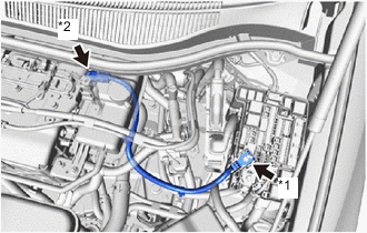
*1 AMD Terminal (Motor Compartment Relay Block Side) *2 AMD Terminal (Inverter with Converter Assembly Side) Be sure to disconnect the cable from the negative (-) terminal of the auxiliary battery before disconnecting the AMD terminal from the motor compartment relay block.
Note
After turning the power switch off, waiting time may be required before disconnecting the cable from the negative (-) auxiliary battery terminal. Therefore, make sure to read the disconnecting the cable from the negative (-) auxiliary battery terminal notices before proceeding with work.
-
After disconnecting the AMD terminal, wrap the terminal with insulation tape.
-
Be sure to reconnect the AMD terminal to the motor compartment relay block before reconnecting the cable to the negative (-) terminal of the auxiliary battery.
Note
Be sure to reconnect the AMD terminal to the motor compartment relay block before reconnecting the cable to the negative (-) terminal of the auxiliary battery.
-
-
PRECAUTIONS FOR WORKING IN MOTOR ROOM
CAUTION:
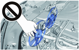
The electric fans may be activated unintentionally. Thus, keep your hands and tools away from the fans.
-
PRECAUTIONS FOR REPLACING EV CONTROL ECU
-
Perform Registration (VIN registration) when replacing the EV control ECU.
-
-
DISCONNECTING AND RECONNECTING NEGATIVE AUXILIARY BATTERY CABLE
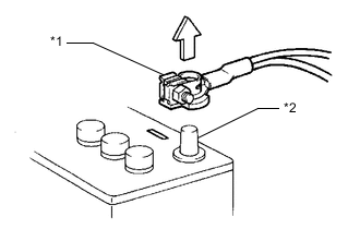
*1 Cable *2 Negative (-) Battery Terminal
-
Before performing work on electronic components, disconnect the cable from the negative (-) auxiliary battery terminal to prevent damage to the electrical system or electrical components.
-
Before disconnecting and reconnecting the auxiliary battery cable, turn the power switch off and the headlight switch off. Then loosen the terminal nut completely. Do not damage the cable or terminal.
-
When the auxiliary battery cable is disconnected, the clock and radio settings and stored DTCs are cleared. Therefore, before disconnecting the auxiliary battery cable, make a note of them.
Note
-
After turning the power switch off, waiting time may be required before disconnecting the cable from the negative (-) auxiliary battery terminal. Therefore, make sure to read the disconnecting the cable from the negative (-) auxiliary battery terminal notices before proceeding with work.
-
When the cable is disconnected from the negative (-) auxiliary battery terminal, initialize the following systems after the cable is reconnected.
-
-