FC STACK INSTALLATION

PROCEDURE
-
INSTALL FC CONVERTER COOLING WATER INLET PIPE
Tech Tips
This procedure is only performed if the FC stack assembly was replaced with a new one.
-
Engage the 2 clamps to install the FC converter cooling water inlet pipe to the wire harness.
-
-
INSTALL NO. 1 FC STACK CAUTION LABEL
Tech Tips
This procedure is only performed if the FC stack assembly was replaced with a new one.
-
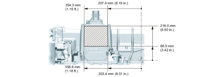
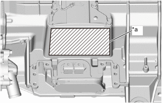
Install a new No. 1 FC stack caution label to the FC stack assembly in the location indicated in the illustration.
Note
-
Do not allow grease, oil or foreign matter to adhere to the FC stack assembly.
-
When peeling the No. 1 fuel stack caution label off of the backing paper, do not allow grease, oil or foreign matter to adhere to the adhesive portion of the No. 1 FC stack caution label.
-
Apply sufficient pressure when attaching the No. 1 FC stack caution label to ensure proper adhesion.
-
When applying the No. 1 FC stack caution label, be careful to avoid wrinkles or air bubbles.
-
When the No. 1 FC stack caution label is removed, it will be deformed and lose adhesive strength, so it cannot be reused.
-
If the area around the No. 1 FC stack caution label is extremely hot, then after applying the label, check for peeling, discoloration, deformation of lettering, dirtiness, etc., and if the visual appearance of the label is poor, replace it with a new No. 1 FC stack caution label.
-
Apply the No. 1 FC stack caution label in the label application area, and do not apply it onto rounded areas or protrusions.
-
-
-
INSTALL FC STACK ASSEMBLY

Front Side of Vehicle 
Attachment installation position CAUTION:
Wear insulated gloves.
-
Visually inspect the rear frame assembly.
-
Visually inspect the rear frame assembly to make sure there are no scratches or other damage.
OK Make sure that there are no cracks, creases or uneven surfaces, and no scratches with depth of 1.0 mm (0.0394 in.) or more, or length of 60.0 mm (2.36 in.) or more. Tech Tips
If the result is not as specified, replace the rear frame assembly.
-
-
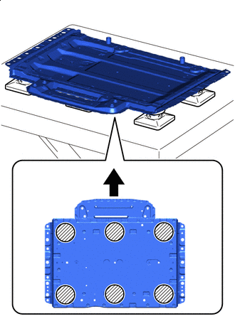
Using the height adjustment attachment, set the rear frame assembly on the engine lifter.
Note
Set so that the rear frame assembly is horizontal and level.
-
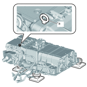
*a Eye Bolt Install an eye bolt in the location shown in the illustration.
Tech Tips
Eye Bolt Installation Hole SizeNominal Diameter [mm] Pitch [mm] Depth [mm] M10 1.5 18 -
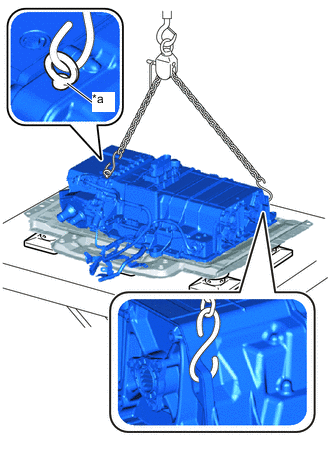
*a Eye Bolt Using an engine sling device, set it in the location shown in the illustration, and install the FC stack assembly to the rear frame assembly.
Note
-
Do not hoist the FC stack assembly from locations other than those shown in the illustration.
-
Make sure that wire harnesses are not caught when hoisting.
-
To avoid damaging or deforming the FC stack assembly, be careful of the hoisting angle of the engine sling device.
-
Set the engine sling device so that the FC stack assembly is horizontal and level.
-
-
Remove an eye bolt.
-
Install the 3 No. 2 FC stack mounts to the FC stack assembly.
-
Temporarily tighten the 3 bolts.
Tech Tips
Perform full tightening after installing the FC converter assembly.
-
-
INSTALL NO. 1 HYDROGEN SUPPLY TUBE SUB-ASSEMBLY
-
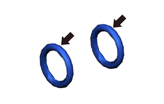
Apply TOYOTA Genuine FC Grease to 2 new O-rings.
-
To prevent contamination by foreign matter or water droplets, remove the plastic bag from the No. 1 hydrogen supply tube sub-assembly immediately before performing the procedure.
-
Install the 2 O-rings to the No. 1 hydrogen supply tube sub-assembly.
Note
During installation, be careful not to damage the O-rings.
-
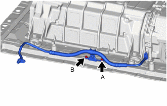
Temporarily install the No. 1 hydrogen supply tube sub-assembly to the rear frame assembly with the bolt A.
-
Install the bolt B.
- Torque:
- 8.5 N*m { 87 kgf*cm, 75 in.*lbf }
-
Fully tighten the bolt A.
- Torque:
- 8.5 N*m { 87 kgf*cm, 75 in.*lbf }
-
To prevent contamination by foreign matter or water droplets, remove the protective tape from the connecting portion of the FC stack assembly immediately before performing the procedure.
-
Connect the No. 1 hydrogen supply tube sub-assembly to the FC stack assembly with the bolt.
- Torque:
- 8.5 N*m { 87 kgf*cm, 75 in.*lbf }
Note
Make sure that the O-rings and engagement portions have no damage or foreign matter.
-
-
INSTALL NO. 1 FC EXHAUST PIPE
-
INSTALL FC STACK AIR INLET HOSE
-
To prevent contamination by foreign matter or water droplets, remove the plastic bags from the connecting portions of the FC stack air inlet hose and FC stack assembly immediately before performing the procedure.
-
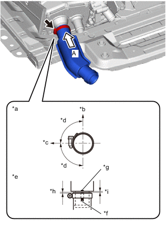
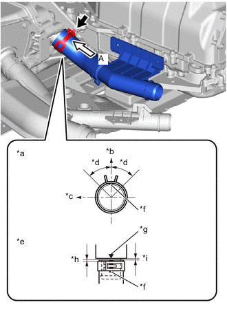
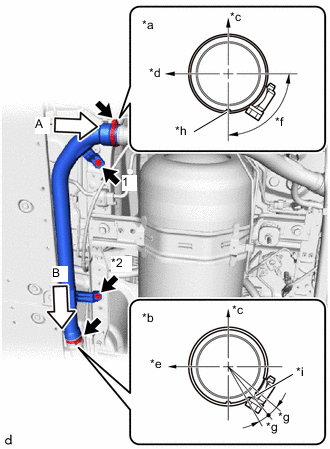
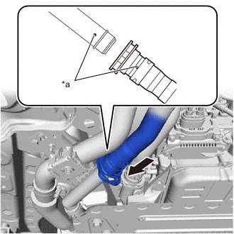
*a View A *b Upper Side of Vehicle *c RH Side of Vehicle *d Area of threaded portion of hose clamp: 90° *e Locations of hose tip and hose clamp *f Paint Mark (Yellow) *g Matchmark *h Distance between hose tip and hose clamp location: 2.0 to 5.0 mm (0.0787 to 0.197 in.) *i Distance between hose tip and FC stack assembly location: 0 to 2.0 mm (0 to 0.0787 in.) Install the FC stack air inlet hose to the FC stack assembly and tighten the hose clamp.
- Torque:
- 6.3 N*m { 64 kgf*cm, 56 in.*lbf }
Note
Perform the installation with the hose and hose clamp at the correct angle.
-
-
INSTALL FC STACK COOLING WATER OUTLET HOSE
-
To prevent contamination by foreign matter, remove the plastic bags from the connecting portions of the FC stack cooling water outlet hose and FC stack assembly immediately before performing the procedure.
-
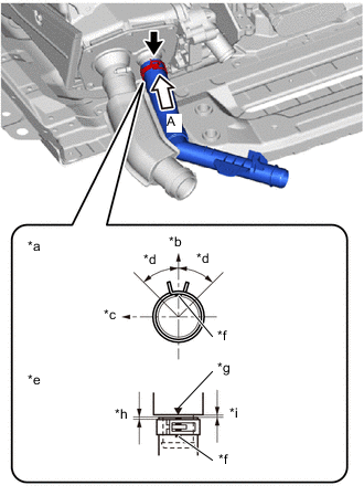
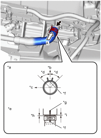
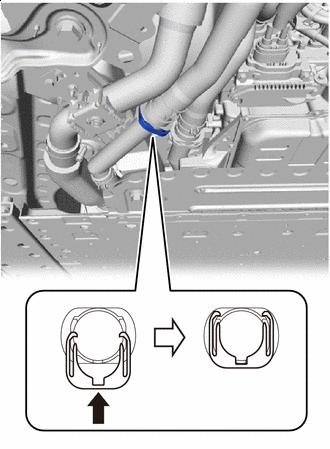
*a View A *b Upper Side of Vehicle *c RH Side of Vehicle *d Area of claw of hose clip: 45° *e Locations of hose tip and hose clip *f Paint Mark (White) *g Matchmark *h Distance between hose tip and hose clip location: 2.0 to 5.0 mm (0.0787 to 0.197 in.) *i Distance between hose tip and FC stack assembly location: 0 to 2.0 mm (0 to 0.0787 in.) Install the FC stack cooling water outlet hose to the FC stack assembly and slide the hose clip to secure it.
Note
Perform the installation with the hose and hose clip at the correct angle.
Tech Tips
When connecting, if it is difficult to insert the FC stack cooling water outlet hose, coat it with new coolant (Toyota genuine FC stack coolant)
-
-
INSTALL FC CONVERTER ASSEMBLY
CAUTION:
Wear insulated gloves.
-
To prevent contamination by foreign matter or water droplets, remove the protective tape from the opening of the FC converter assembly immediately before performing the procedure.
-
Install a new rear FC converter gasket to the FC converter assembly.
Note
-
Do not allow foreign matter to adhere to the surface of the rear FC converter gasket.
-
Perform the procedures by hand. Do not use any tools.
-
Securely press the rear FC converter gasket into the groove of the FC converter assembly to install it.
-
-
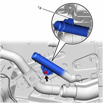
To prevent contamination by foreign matter or water droplets, remove the protective tape from the opening of the FC stack assembly immediately before performing the procedure.
-
*a Protective Tape To avoid damaging the No. 1 FC stack caution label, protect the No. 1 FC stack caution label using protective tape or similar.
Tech Tips
This procedure is only performed if the FC stack assembly was replaced with a new one. (When the FC stack assembly is not replaced, it is performed during the FC stack assembly removal procedure.)
-
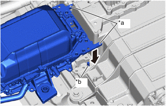
*a Rough Guide *b Assembly Guide Pin Lower Vertically Using the rough guide, align the FC converter assembly with the installation position, lower the FC converter assembly vertically and securely engage the assembly guide pin.
Note
-
Do not hold the FC converter assembly by its pipe portion.
-
Be careful not to drop the rear FC converter gasket.
-
Be careful that foreign matter or water droplets do not enter the FC stack assembly and FC converter assembly.
-
If the FC converter assembly has been dropped, damaged or subjected to a strong impact, replace it with a new one.
-
-
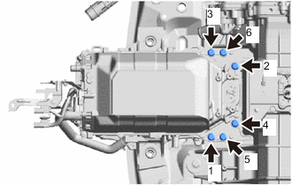
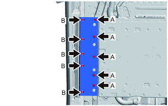
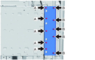
Install the 6 bolts in the order shown in the illustration.
- Torque:
- 62 N*m { 632 kgf*cm, 46 ft.*lbf }
-
Remove the protective tape or similar from the No. 1 FC stack caution label.
-
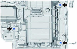
Install the 2 No. 2 FC stack mounts to the FC converter assembly.
-
Install the 2 bolts.
- Torque:
- 50 N*m { 510 kgf*cm, 37 ft.*lbf }
-
To prevent contamination by foreign matter or water droplets, remove the protective tape from the opening of the FC converter assembly immediately before performing the procedure.
-
Using an insulated tool, install the 2 bolts.
- Torque:
- 8.0 N*m { 82 kgf*cm, 71 in.*lbf }
-
Install a new rear FC converter service hole gasket to the rear FC converter service hole cover.
Note
-
Do not allow foreign matter to adhere to the rear FC converter service hole gasket.
-
Perform the procedures by hand. Do not use any tools.
-
Securely press the rear FC converter service hole gasket into the groove of the rear FC converter service hole cover to install it.
-
-
Install the rear FC converter service hole cover to the FC converter assembly with the 2 bolts.
- Torque:
- 8.0 N*m { 82 kgf*cm, 71 in.*lbf }
Note
-
Be careful that foreign matter or water droplets do not enter the FC converter assembly.
-
Be careful not to drop the rear FC converter service hole gasket.
-
Fully tighten the 3 bolts.
- Torque:
- 50 N*m { 510 kgf*cm, 37 ft.*lbf }
-
-
INSTALL FC STACK COOLING WATER INLET HOSE
-
To prevent contamination by foreign matter, remove the plastic bags from the connecting portions of the FC stack cooling water inlet hose and FC stack assembly immediately before performing the procedure.
-
*a View A *b Upper Side of Vehicle *c RH Side of Vehicle *d Area of claw of hose clip: 45° *e Locations of hose tip and hose clip *f Paint Mark (Yellow) *g Matchmark *h Distance between hose tip and hose clip location: 2.0 to 5.0 mm (0.0787 to 0.197 in.) *i Distance between hose tip and FC stack assembly location: 0 to 2.0 mm (0 to 0.0787 in.) Install the FC stack cooling water inlet hose to the FC stack assembly and slide the hose clip to secure it.
Note
Perform the installation with the hose and hose clip at the correct angle.
Tech Tips
When connecting, if it is difficult to insert the FC stack cooling water inlet hose, coat it with new coolant (Toyota genuine FC stack coolant)
-
-
CONNECT FC STACK COOLING WATER INLET PIPE
-
Connect the FC stack cooling water inlet pipe to the FC converter assembly with the 2 bolts.
- Torque:
- 8.0 N*m { 82 kgf*cm, 71 in.*lbf }
-
-
INSTALL WIRE HARNESS CLAMP BRACKET
-
Install the wire harness clamp bracket to the FC stack assembly with the bolt.
- Torque:
- 8.0 N*m { 82 kgf*cm, 71 in.*lbf }
-
Engage the 3 clamps to install the 3 wire harness clamp brackets to the wire harness.
-
-
CONNECT WIRE HARNESS
CAUTION:
Wear insulated gloves.
-
Engage the 2 clamps to connect the wire harness to the wire harness clamp bracket.
-
To prevent contamination by foreign matter, remove the plastic bags from the connecting portions of the FC converter cooling water inlet hose and FC converter assembly immediately before performing the procedure.
-
*a View A *b Upper Side of Vehicle *c Front Side of Vehicle *d Area of claw of hose clip: 45° *e Locations of hose tip and hose clip *f Paint Mark (Yellow) *g Matchmark *h Distance between hose tip and hose clip location: 2.0 to 5.0 mm (0.0787 to 0.197 in.) *i Distance between hose tip and FC converter assembly location: 0 to 2.0 mm (0 to 0.0787 in.) Connect the FC converter cooling water inlet hose to the FC converter assembly and slide the hose clip to secure it.
Note
Perform the installation with the hose and hose clip at the correct angle.
-
Install the wire harness clamp bracket to the FC converter assembly with the bolt.
- Torque:
- 8.0 N*m { 82 kgf*cm, 71 in.*lbf }
-
Connect the FC converter cooling water inlet pipe, together with the wire harness, to the FC converter assembly with the 2 bolts.
- Torque:
- 8.0 N*m { 82 kgf*cm, 71 in.*lbf }
-
Connect the connector.
-
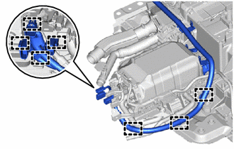
Engage the 7 clamps to connect the wire harness to the wire harness clamp bracket.
-
Install the 3 wire harness clamp brackets to the FC converter assembly and FC stack assembly with the 3 bolts.
- Torque:
- 8.0 N*m { 82 kgf*cm, 71 in.*lbf }
-
Engage the 7 clamps to connect the wire harness and connector to the FC converter assembly and FC stack assembly.
-
-
INSTALL REAR FRAME ASSEMBLY
-
Check that the FC stack with FC converter assembly, together with the rear frame assembly, are set level and horizontal on an engine lifter.
-
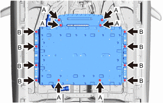
Operate the engine lifter, and with the 14 bolts, install the rear frame assembly, together with the FC stack with FC converter assembly, to the vehicle.
- Torque:
- Bolt A
- 82 N*m { 836 kgf*cm, 60 ft.*lbf }
- Bolt B
- 74 N*m { 755 kgf*cm, 55 ft.*lbf }
Note
-
To prevent them from falling over, securely support the FC stack with FC converter assembly together with the rear frame assembly.
-
Be careful of the wire harnesses and hoses when installing.
Bolt Length Item Length Bolt A 79 mm (3.11 in.) Bolt B 39 mm (1.54 in.)
-
-
INSTALL FRAME REAR CROSSMEMBER EXTENSION RH
-
Install the frame rear crossmember extension RH to the vehicle with the 10 bolts.
- Torque:
- 23 N*m { 235 kgf*cm, 17 ft.*lbf }
Bolt Length Item Length Bolt A 50 mm (1.97 in.) Bolt B 28 mm (1.18 in.)
-
-
INSTALL FRAME REAR CROSSMEMBER EXTENSION LH
-
Install the frame rear crossmember extension LH to the vehicle with the 10 bolts.
- Torque:
- 23 N*m { 235 kgf*cm, 17 ft.*lbf }
Note
Be careful of the brake tube when installing.
Bolt Length Item Length Bolt A 50 mm (1.97 in.) Bolt B 28 mm (1.18 in.)
-
-
CONNECT NO. 1 HYDROGEN SUPPLY TUBE SUB-ASSEMBLY
-
CONNECT NO. 2 HYDROGEN SUPPLY TUBE SUB-ASSEMBLY
-
CONNECT NO. 3 PARKING BRAKE CABLE ASSEMBLY
-
Connect the No. 3 parking brake cable assembly to the vehicle with the bolt.
- Torque:
- 6.0 N*m { 61 kgf*cm, 53 in.*lbf }
-
-
INSTALL NO. 2 FC EXHAUST PIPE
-
To prevent contamination by foreign matter, remove the plastic bag from the connecting portion of the No. 1 FC exhaust pipe immediately before performing the procedure.
-
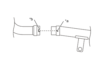
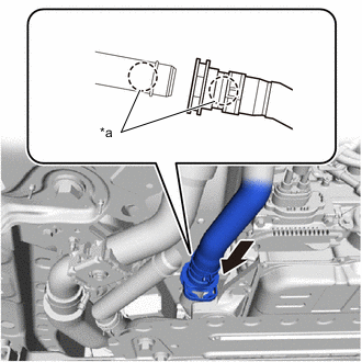
*a No. 2 FC Exhaust Pipe Triangle Mark *b No. 1 FC Exhaust Pipe Groove Connect the No. 2 FC exhaust pipe to the No. 1 FC exhaust pipe.
Note
-
Make sure not to scratch or damage the No. 1 FC exhaust pipe and No. 2 FC exhaust pipe.
-
Check that the rubber portion of the No. 1 FC exhaust pipe connecting portion (No. 2 FC exhaust pipe connecting side) is not folded to the inside, is securely assembled, and covers the entire circumference.
Tech Tips
As shown in the illustration, align the triangle mark of the No. 2 FC exhaust pipe with the position of the groove of the No. 1 FC exhaust pipe.
-
-
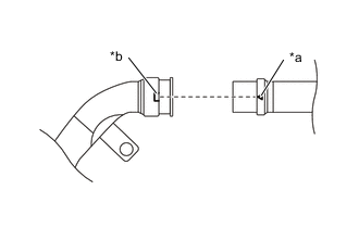
*a No. 3 FC Exhaust Pipe Triangle Mark *b No. 2 FC Exhaust Pipe Groove Connect the No. 2 FC exhaust pipe to the No. 3 FC exhaust pipe.
Note
-
Make sure not to scratch or damage the No. 2 FC exhaust pipe and No. 3 FC exhaust pipe.
-
Check that the rubber portion of the No. 2 FC exhaust pipe connecting portion (No. 3 FC exhaust pipe connecting side) is not folded to the inside, is securely assembled, and covers the entire circumference.
Tech Tips
As shown in the illustration, align the triangle mark of the No. 3 FC exhaust pipe with the position of the groove of the No. 2 FC exhaust pipe.
-
-
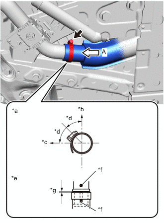
*a View A *b View B *c Upper Side of Vehicle *d Right Side of Vehicle *e Front Side of Vehicle *f Clamp bolt must be within this range (90°) *g Clamp bolt flange surface must be within this range (10°) *h No. 2 FC Exhaust Pipe Groove *i No. 1 FC Exhaust Pipe Protrusion Temporarily install the No. 2 FC exhaust pipe to the vehicle body with the 2 bolts.
-
Fully tighten the 2 bolts in the order shown in the illustration.
- Torque:
- 5.0 N*m { 51 kgf*cm, 44 in.*lbf }
-
Tighten the 2 clamps.
- Torque:
- 3.0 N*m { 31 kgf*cm, 27 in.*lbf }
Note
-
If the clamp is damaged or rusty, replace it with a new one.
-
Align the clamp with the position shown in the illustration, and install the clamp.
-
Try to move the clamp by hand and confirm that it does not rotate.
-
-
CONNECT FC STACK COOLING WATER OUTLET PIPE
-
*a Detent Connect the FC stack cooling water outlet pipe to the vehicle with the bolt.
- Torque:
- 8.0 N*m { 82 kgf*cm, 71 in.*lbf }
Note
After installing, check that the detent of the FC stack cooling water outlet pipe is contacting the vehicle body.
-
-
CONNECT FC STACK AIR INLET HOSE
-
To prevent contamination by foreign matter or water droplets, remove the plastic bags from the connecting portions of the FC stack air inlet hose and No. 2 FC air compressor outlet pipe immediately before performing the procedure.
-
*a View A *b Upper Side of Vehicle *c LH Side of Vehicle *d Area of threaded portion of hose clamp: 45° *e Locations of hose tip and hose clamp *f Paint Mark (White) *g Distance between hose tip and hose clamp location: 2.0 to 5.0 mm (0.0787 to 0.197 in.) Connect the FC stack air inlet hose to the No. 2 FC air compressor outlet pipe and tighten the hose clamp.
- Torque:
- 6.3 N*m { 64 kgf*cm, 56 in.*lbf }
Note
Perform the installation with the hose and hose clamp at the correct angle.
-
-
CONNECT WIRE HARNESS
CAUTION:
Wear insulated gloves.
-
Engage the clamp to connect the wire harness to the wire harness clamp bracket.
-
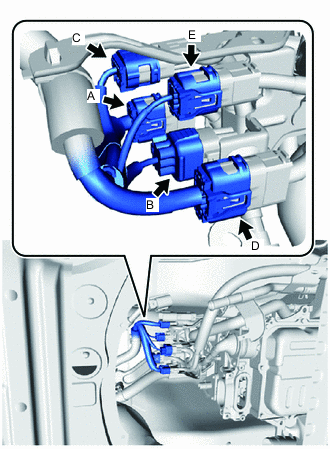
Connect the 5 connectors.
Note
-
Do not touch the connector terminals.
-
Because there are multiple connectors, make sure to connect them to their original locations.
HINT Connector Connector Color Connector Pin Count A Black 13P B Gray 6P C Black 10P D Gray 13P E Gray 8P -
-
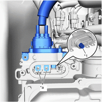
*1 Green-colored Lock Connect the connector and press in the green lock to securely fix the connector in place as shown in the illustration.
Note
-
Do not touch the connector terminals.
-
Check that the connector is securely connected.
-
-
-
CONNECT NO. 2 EV WATER HOSE CONNECTOR
-
To prevent contamination by foreign matter, remove the plastic bags from the connecting portions of the No. 2 EV water hose connector and FC converter assembly immediately before performing the procedure.
-
Connect the No. 2 EV water hose connector together with the FC converter cooling water outlet hose.
Note
If the 2 O-rings on the inner side of the No. 2 EV water hose connector are damaged or falling out, replace the No. 2 EV water hose connector with a new one.
-
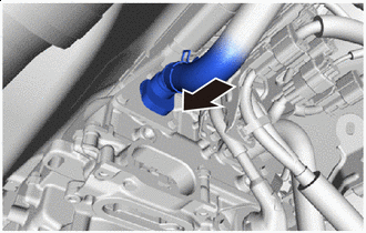
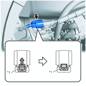
Insert Slowly Align the No. 2 EV water hose connector with the connecting portion of the FC converter assembly, and press it in as a single unit.
Note
Securely insert the No. 2 EV water hose connector all the way into the connecting portion of the FC converter assembly.
-
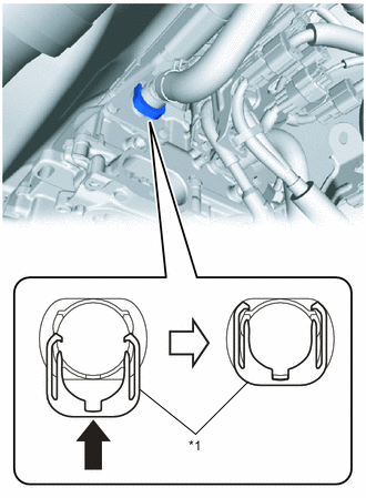
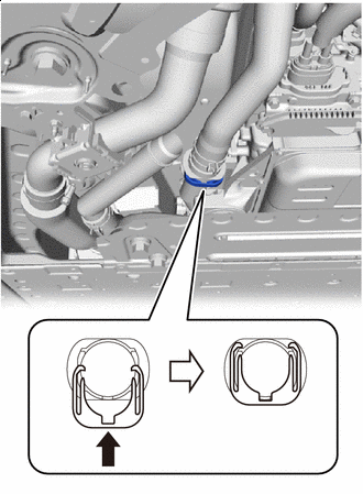
*1 Retainer Push Up Push up the retainer of the No. 2 EV water hose connector and lock it.
Tech Tips
The retainer of the No. 2 EV water hose connector is designed so that it cannot be locked unless the No. 2 EV water hose connector is securely inserted into the FC converter assembly.
-
Pull on the No. 2 EV water hose connector and check that it is securely connected.
-
-
-
CONNECT NO. 2 INVERTER COOLING OUTLET HOSE
-
To prevent contamination by foreign matter, remove the plastic bags from the connecting portions of the No. 2 inverter cooling outlet hose and FC converter cooling water inlet pipe immediately before performing the procedure.
-
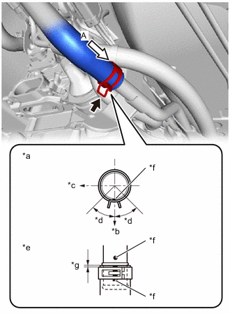
*a View A *b Lower Side of Vehicle *c RH Side of Vehicle *d Area of claw of hose clip: 45° *e Locations of hose tip and hose clip *f Paint Mark (Yellow) *g Distance between hose tip and hose clip location: 2.0 to 5.0 mm (0.0787 to 0.197 in.) Connect the No. 2 inverter cooling outlet hose to the FC converter cooling water inlet pipe and slide the hose clip to secure it.
Note
Perform the installation with the hose and hose clip at the correct angle.
-
-
CONNECT FC CONVERTER POWER OUTLET CABLE
CAUTION:
Wear insulated gloves.
-
To prevent contamination by foreign matter or water droplets, remove the protective tape from the openings of the FC converter assembly immediately before performing the procedure.
-
*1 Interlock Connector *a Terminal Portion Connect the FC converter power outlet cable to the FC converter assembly.
Note
-
Do not touch the rubber seal or terminal portion of the FC converter power outlet cable.
-
Do not apply any impacts to the terminal portion of the FC converter power outlet cable.
-
Do not scratch or damage the FC converter assembly with the terminal portion of the FC converter power outlet cable.
-
Securely connect the interlock connector.
-
Check that the terminal of the FC converter power outlet cable can be seen from the installation area of the front FC converter service hole cover.
-
-
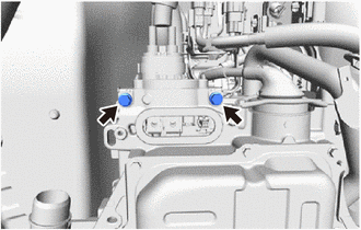
Using an insulated tool, install the 2 bolts.
- Torque:
- 8.0 N*m { 82 kgf*cm, 71 in.*lbf }
-
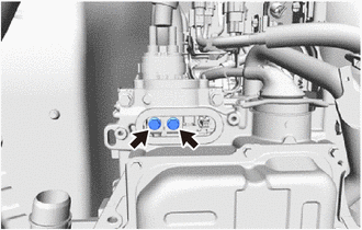
Using an insulated tool, install the 2 bolts.
- Torque:
- 8.0 N*m { 82 kgf*cm, 71 in.*lbf }
-
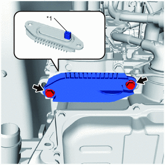
*1 Interlock Connector Install the front FC converter service hole cover to the FC converter assembly with the 2 bolts.
- Torque:
- 8.0 N*m { 82 kgf*cm, 71 in.*lbf }
Note
-
Do not allow foreign matter to adhere to the surface of the gasket of the front FC converter service hole cover.
-
Securely connect the interlock connector.
-
Make sure not to drop the gasket of the front FC converter service hole cover.
-
-
INSTALL INVERTER COVER
-
CONNECT WIRE HARNESS
-
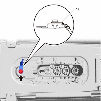
*a Detent Connect the wire harness to the vehicle with the bolt.
- Torque:
- 8.4 N*m { 86 kgf*cm, 74 in.*lbf }
Note
Install with the wire harness detent contacting as shown in the illustration.
-
-
INSTALL FC STACK SERVICE PLUG GRIP
-
INSTALL SERVICE PLUG GRIP (for EV)
-
CHECK FOR HYDROGEN GAS LEAK
-
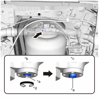
*a Adjustment Bolt *b Manual Valve Closed *c Manual Valve Open *d Counterclockwise Using an 8 mm socket hexagon wrench, rotate the adjustment bolt counterclockwise, and open the No. 1 hydrogen tank assembly manual valve.
Note
-
The manual valve shuts off the pressure from the hydrogen tank assembly, so be careful not to damage the hexagonal portion.
-
If the hexagonal portion is damaged, it will be impossible to operate the adjustment bolt.
-
Do not rotate the adjustment bolt more than 4 rotations.
-
Rotating the adjustment bolt more than 4 rotations could damage the manual valve.
-
If the manual valve is damaged, it will be necessary to replace the No. 1 hydrogen tank assembly.
-
-
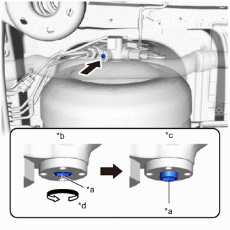
*a Adjustment Bolt *b Manual Valve Closed *c Manual Valve Open *d Counterclockwise Using an 8 mm socket hexagon wrench, rotate the adjustment bolt counterclockwise, and open the No. 2 hydrogen tank assembly manual valve.
Note
-
The manual valve shuts off the pressure from the hydrogen tank assembly, so be careful not to damage the hexagonal portion.
-
If the hexagonal portion is damaged, it will be impossible to operate the adjustment bolt.
-
Do not rotate the adjustment bolt more than 4 rotations.
-
Rotating the adjustment bolt more than 4 rotations could damage the manual valve.
-
If the manual valve is damaged, it will be necessary to replace the No. 2 hydrogen tank assembly.
-
-
Open the tank shut valves of the No. 1 and No. 2 hydrogen tank assemblies, and after 2 to 3 seconds, close the tank shut valves again.
Note
If the Data List item "Medium-range Hydrogen Pressure (gauge)" decreases to below 0.6 MPa (6.1 kgf/cm2, 87 psi) the tank shut valves of the No. 1 and No. 2 hydrogen tank assemblies will forcibly close.
Tech Tips
This is done to fill the hydrogen piping with hydrogen gas.
-
If the tank shut valves of the No. 1 and No. 2 hydrogen tank assemblies do not open, open the tank shut valves again, and after 2 to 3 seconds, close the tank shut valves.
-
Blow compressed air around the underside of the vehicle.
Tech Tips
To enable accurate detection of hydrogen gas leaks from the piping, blow compressed air from the front of the vehicle towards the rear.
-
If there are water droplets, etc. adhering to any of the measurement locations, wipe them away before performing the procedures.
Note
If measurements are performed while water droplets, etc. are adhered, the hydrogen gas detector may be damaged.
-
Using SST and a hydrogen gas detector, measure each of the measurement locations for approximately 10 continuous seconds per location.
- SST
- 09401-62010
Note
-
Figure 1. <Hydrogen Gas Detector Contact Location and Direction>
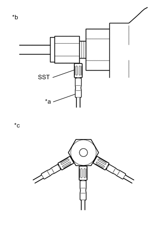
*a Hydrogen Gas Detector *b Side View *c Cutaway View To perform the measurement, hold the tip of the hydrogen gas detector as shown in the illustration (*c), in contact with a single location from any one of the directions shown.
-
Hold the tip in light contact with the location so that the tip does not deform.
Tech Tips
-
Immediately after the measurement starts, the measured value may be unstable.
-
If the value is outside the specified range, replace the leaking component with a new one, and perform the hydrogen gas leak check again.
Figure 2. <Measurement Locations>
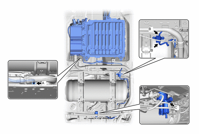
Measurement Location and Direction - - Illustration Item Measurement Location Measurement Method Specified Value A Connection between FC Stack Assembly and No. 1 Hydrogen Supply Tube Sub-assembly Measure the area near the piping, connecting portion, or sensor connecting portion. 300 ppm or less B Connection between No. 1 Hydrogen Supply Tube Sub-assembly and No. 2 Hydrogen Supply Tube Sub-assembly C Medium Pressure Port of Hydrogen Supply Regulator Assembly
*1
-
*1: If the value is not as specified, replace the O-ring of the medium pressure port.
-
-
CONNECT NO. 2 FC COOLING WATER PUMP OUTLET HOSE
-
Connect the No. 2 FC cooling water pump outlet hose (with FC water hose connector).
-
Remove the plastic bags that are protecting the connecting portions of the No. 2 FC cooling water pump outlet hose (with FC water hose connector) and FC stack cooling water inlet pipe.
-
*a No Identification Markings Slowly Insert Line up the No. 2 FC cooling water pump outlet hose (with FC water hose connector) and FC stack cooling water inlet pipe in a row, and push them in as a single unit.
Note
-
The No. 2 FC cooling water pump outlet hose (with FC water hose connector) and FC stack cooling water inlet pipe do not have identification markings.
-
If the O-ring on the inner side of the FC water hose connector is damaged or falls out, replace the FC water hose connector with a new one.
-
Do not rotate or tilt the No. 2 FC cooling water pump outlet hose (with FC water hose connector) when pushing it in.
-
Securely and fully insert the No. 2 FC cooling water pump outlet hose (with FC water hose connector) all the way into the FC stack cooling water inlet pipe.
-
-
Push Up Push up the retainer of the FC water hose connector and lock it.
Tech Tips
The retainer of the FC water hose connector is designed so that it cannot be locked if the No. 2 FC cooling water pump outlet hose (with FC water hose connector) is not securely inserted into the FC stack cooling water inlet pipe.
-
After connecting the No. 2 FC cooling water pump outlet hose (with FC water hose connector), firmly pull on the FC water hose connector and FC stack cooling water inlet pipe to check that they are securely connected.
-
-
-
CONNECT NO. 2 FC COOLING WATER VALVE INLET HOSE
-
Connect the No. 2 FC cooling water valve inlet hose (with FC water hose connector).
-
Remove the plastic bags that are protecting the connecting portions of the No. 2 FC cooling water pump inlet hose (with FC water hose connector) and FC stack cooling water outlet pipe.
-
*a Identification Markings (White) Slowly Insert Line up the No. 2 FC cooling water valve inlet hose (with FC water hose connector) and FC stack cooling water outlet pipe in a row, and push them in as a single unit.
Note
-
Align the white identification markings of the No. 2 FC cooling water valve inlet hose (with FC water hose connector) and the FC stack cooling water outlet pipe.
-
If the O-ring on the inner side of the FC water hose connector is damaged or falls out, replace the FC water hose connector with a new one.
-
Do not rotate or tilt the No. 2 FC cooling water pump outlet hose (with FC water hose connector) when pushing it in.
-
Securely and fully insert the No. 2 FC cooling water pump inlet hose (with FC water hose connector) all the way into the FC stack cooling water outlet pipe.
-
-
Push Up Push up the retainer of the FC water hose connector and lock it.
Tech Tips
The retainer of the FC water hose connector is designed so that it cannot be locked if the No. 2 FC cooling water pump inlet hose (with FC water hose connector) is not securely inserted into the FC stack cooling water outlet pipe.
-
After connecting the No. 2 FC cooling water pump inlet hose (with FC water hose connector), firmly pull on the FC water hose connector and FC stack cooling water outlet pipe to check that they are securely connected.
-
-
-
ADD COOLANT (for Inverter)
-
ADD COOLANT (FC STACK COOLANT)
-
INSPECT FOR COOLANT LEAK (for Inverter)
-
INSPECT FOR COOLANT (FC STACK COOLANT)
-
INSTALL NO. 1 FLOOR UNDER COVER
-
INSTALL NO. 2 FLOOR UNDER COVER
-
INSTALL FRONT FLOOR CENTER COVER RH
-
INSTALL FRONT FLOOR CENTER COVER LH
-
INSTALL SUSPENSION MEMBER TO FRONT CROSSMEMBER BRACE SUB-ASSEMBLY
-
INSTALL FRONT FLOOR COVER RH
-
INSTALL FRONT FLOOR COVER LH
-
INSTALL NO. 2 MOTOR UNDER COVER
-
INSTALL NO. 3 RADIATOR AIR GUIDE
-
INSTALL FRONT BUMPER LOWER ABSORBER
-
INITIALIZATION
-
Perform the following procedures after replacing the FC stack assembly.
-
Using the GTS, perform the utility "FC Stack Shock History Clear".
-
-