SERVICE PLUG GRIP REMOVAL
CAUTION / NOTICE / HINT
CAUTION:
-
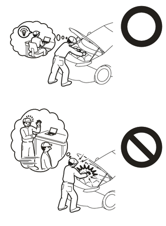
This vehicle contains high voltage circuits standardized with orange colored wiring and connectors, so follow the instructions in this manual to perform the procedures correctly.
-
If the correct procedures are not followed according to the instructions in this manual, there is a danger of electric shock from the high voltage circuits.
-

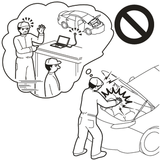
Be sure to wear insulating gloves when working on high voltage wiring or components.
-
If work is performed without wearing insulating gloves, there is a danger of electric shock.
PROCEDURE
-
PRECAUTION
Note
After turning the power switch off, waiting time may be required before disconnecting the cable from the negative (-) auxiliary battery terminal. Therefore, make sure to read the disconnecting the cable from the negative (-) auxiliary battery terminal notices before proceeding with work.
-
CHECK FOR DTC
-
Check for DTCs.
Powertrain > EV > Trouble CodesCAUTION:
-
Before installing or removing any components of the high voltage system, make sure to check the DTCs and confirm that P0AA6 (High Voltage System Insulation Malfunction) has not been output. If it has been output, perform troubleshooting for that DTC first.
-
If DTC check and troubleshooting are not performed, there is a danger of electric shock due to current leakage.
-
-
-
REMOVE LUGGAGE TRIM SERVICE HOLE COVER
-
DISCONNECT CABLE FROM NEGATIVE AUXILIARY BATTERY TERMINAL
-
REMOVE INTEGRATION CONTROL AND PANEL ASSEMBLY
-
REMOVE FRONT CONSOLE BOX COVER
-
REMOVE CONSOLE COMPARTMENT BOX ASSEMBLY
-
REMOVE NO. 2 CONSOLE BOX DUCT
-
REMOVE NO. 1 CONSOLE BOX DUCT
-
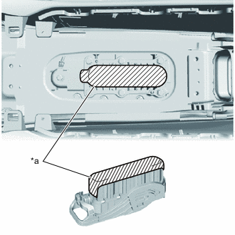
REMOVE FRONT FLOOR SERVICE HOLE COVER
CAUTION:
-
If the front floor service hole cover and surroundings are hot, do not touch them.
-
Touching the front floor service hole cover or surroundings when they are hot could result in burns.
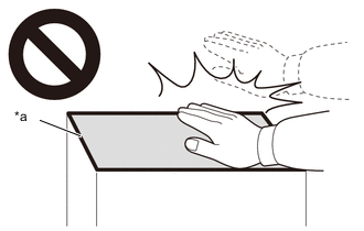
*a High temperature areas
-
Remove the front floor carpet assembly.
-
Remove the 4 bolts and front floor service hole cover from the vehicle.
-
-
REMOVE FRONT FLOOR HOLE SEAL
-
Remove the front floor hole seal from the front floor service hole cover.
-
-
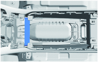
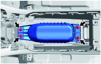
REMOVE FC STACK SERVICE PLUG GRIP
CAUTION:
-

Wear insulated gloves.
-
Do not inspect or repair high voltage system wiring or components without removing the service plug grip (for EV) and FC stack service plug grip.
-
If work is performed while the service plug grip (for EV) and FC stack service plug grip are still installed, high voltage circuits will still be connected and there is a risk of electric shock.
-
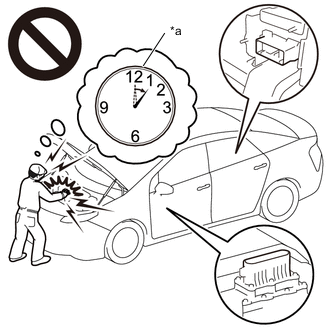
*a Without waiting for 10 minutes After removing both the service plug grip (for EV) and FC stack service plug grip, wait for 10 minutes before touching any high voltage connectors or terminals.
-
If work is performed without waiting for 10 minutes, there is a risk of electric shock due to residual charge in the high voltage capacitors inside the inverter with converter assembly and FC converter assembly.
-

*a High temperature areas If the FC stack service plug grip and surroundings are hot, do not touch them.
-
Touching the FC stack service plug grip or surroundings when they are hot could result in burns.
Note
-
If the power switch is turned on (READY) while the service plug grip (for EV) and FC stack service plug grip are removed, a malfunction may occur. Do not turn the power switch on (READY) unless specifically instructed to do so by the repair manual.
-
Do not touch the terminal portion of the FC stack service plug grip.
-
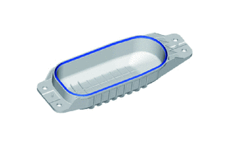
Do not touch the rubber seal of the FC stack service plug grip.
-
Store the removed FC stack service plug grip so that dirt or contaminants do not adhere to its contact points or rubber seal.
-
If the FC stack service plug grip is dropped, scratched, or subjected to a strong impact, replace it with a new one.
Tech Tips
-
The order in which the service plug grip (for EV) and FC stack service plug grip are removed does not matter.
-
The 10 minute wait is to allow the high voltage capacitors inside the inverter with converter assembly and FC converter assembly to discharge.
-
To prevent contamination by foreign matter or water droplets, check that the area around the FC stack service plug grip has no foreign matter or water droplets, and clean away any foreign matter or water droplets found.
Note
Make sure that foreign matter does not enter other components.
-
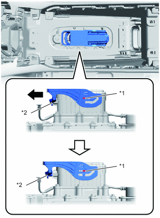
*1 Stopper *2 Interlock Connector 
Sliding Direction Slide the lever of the FC stack service plug grip in the direction shown in the illustration until it contacts the stopper.
Note
The FC stack service plug grip has an interlock connector, so slide it horizontally.
-
After the lever of the FC stack service plug grip contacts the stopper, wait at least 1 second before beginning the next procedure.
Tech Tips
The 1 second delay is the time required for the interlock circuit to disconnect and then for the FC stack circuit to disconnect.
-
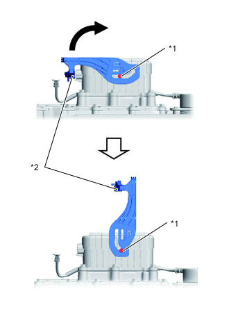
*1 Stopper *2 Interlock Connector Rotating Direction Slowly rotate the lever of the FC stack service plug grip in the direction shown in the illustration until it contacts the stopper.
Note
-
Do not touch the rubber seal of the FC stack service plug grip interlock connector.
-
Do not excessively twist the lever of the FC stack service plug grip.
-
-
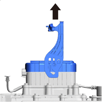
Pull Up Slowly pull the FC stack service plug grip lever straight up vertically to remove the FC stack service plug grip from the FC stack assembly.
-
*a Protective Tape To prevent contamination by foreign matter or water droplets, cover the openings of the removed FC stack service plug grip and FC stack assembly with protective tape.
-
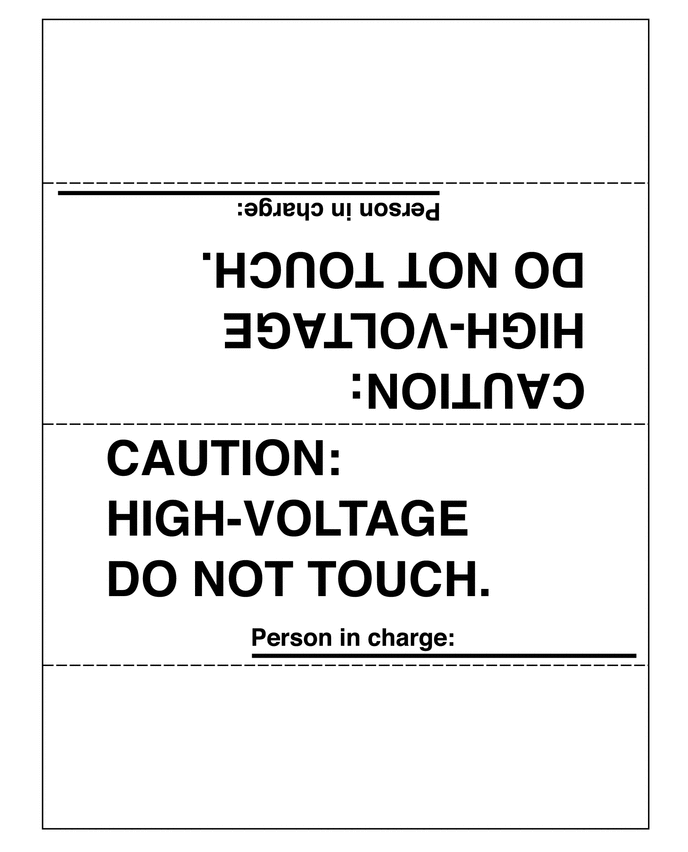
Warn other technicians to be cautious by placing a sign "CAUTION: HIGH VOLTAGE DO NOT TOUCH" on the removed FC stack service plug grip. (An example sign is included, so make a copy and use it.)
-