FC CONTROL SYSTEM, Diagnostic DTC:P0560-117
| DTC Code | DTC Name |
|---|---|
| P0560-117 | System Voltage |
DESCRIPTION
The auxiliary battery supplies electricity to the FC control ECU even when the power switch is off. This power allow the FC control ECU to store data such as DTC history, freeze frame data. If the auxiliary battery voltage falls below a minimum level, the memory is cleared and the FC control ECU determines that there is a malfunction in the power supply circuit.
| DTC No. | Detection Item | DTC Detection Condition | Trouble Area | Warning Indicate |
|---|---|---|---|---|
| P0560-117 | System Voltage | The BATT voltage of the FC control ECU remains at less than 3.5 V for more than 3 seconds. (1 trip detection logic) |
|
Master Warning Light: Comes on |
| Vehicle Condition | FC shutdown (power switch on (IG)) |
FC startup process | FC intermittent operation | FC is generating power (vehicle is in stationary) |
FC is generating power (vehicle is travelling) |
FC shutdown process |
|---|---|---|---|---|---|---|
| Data List "FC Mode" |
FC Shutdown | FC Startup Process | FC Working | FC Shutdown Process | ||
| Data List "FC Intermittent Operation" |
OFF | ON | OFF | OFF | ||
| DTC Detection | ○ | ○ | ○ | ○ | ○ | - |
WIRING DIAGRAM
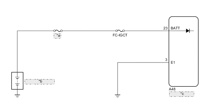
| *a | MAIN |
| *b | Auxiliary Battery |
| *c | FC Control ECU |
CAUTION / NOTICE / HINT
Note
-
Inspect the fuses of circuits related to this system before performing the following procedure.
-
After turning the power switch off, waiting time may be required before disconnecting the cable from the negative (-) auxiliary battery terminal. Therefore, make sure to read the disconnecting the cable from the negative (-) auxiliary battery terminal notices before proceeding with work.
-
When the vehicle is parked with the power switch off, if the FC control ECU judges that the FC stack temperature will go below 0°C (32°F), it activates the FC air compressor, hydrogen pump and FC cooling water pump for a maximum of 180 seconds and drains water from the FC stack assembly. When performing inspection or repairs with the power switch off (not on (IG) or on (READY)), disconnect the cable from the negative (-) auxiliary battery terminal before performing work (If the auxiliary battery voltage is needed to conduct inspection, warm up the FC system beforehand).
Tech Tips
After the repair, clear the DTCs and perform the following procedure to check that DTCs are not output.
-
Turn the power switch off and wait for 3 minutes or more.
-
Turn the power switch on (IG) and wait for 3 seconds or more.
PROCEDURE
-
INSPECT AUXILIARY BATTERY
OK Auxiliary battery is not depleted Result Proceed to OK NG
NG 
CHARGE OR REPLACE AUXILIARY BATTERY
OK 
-
CHECK AUXILIARY BATTERY TERMINAL
OK Auxiliary battery terminals are not loose or corroded. Result Proceed to OK NG
NG
REPAIR OR REPLACE AUXILIARY BATTERY TERMINAL
OK
-
CHECK HARNESS AND CONNECTOR (FC CONTROL ECU - BODY GROUND)
-
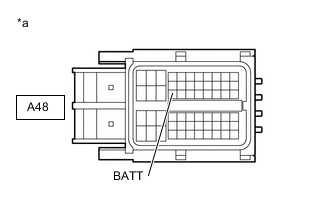
*a Front view of wire harness connector
(to FC Control ECU)
Disconnect the FC control ECU connector.
-
Measure the voltage according to the value(s) in the table below.
Standard Voltage Tester Connection Condition Specified Condition A48-23 (BATT) - Body ground Power switch off 11 to 14 V -
Reconnect the FC control ECU connector.
Result Proceed to OK NG
NG
REPAIR OR REPLACE HARNESS OR CONNECTOR
OK
-
-
CLEAR DTC
-
Connect the GTS to the DLC3.
-
Turn the power switch on (IG).
-
Turn the GTS on.
-
Enter the following menus: Powertrain / FC / Trouble Codes.
-
Clear the DTCs.
Powertrain > FC > Clear DTCs -
Turn the power switch off and wait for 3 minutes or more.
Result Proceed to NEXT
NEXT
-
-
CHECK DTC OUTPUT
-
Connect the GTS to the DLC3.
-
Turn the power switch on (IG) and wait for 3 seconds or more.
-
Turn the GTS on.
-
Enter the following menus: Powertrain / FC / Trouble Codes.
-
Check for DTCs.
Powertrain > FC > Trouble CodesResult Result Proceed to DTC P0560-117 is output A DTCs are not output B -
Turn the power switch off.
A
REPLACE FC CONTROL ECU Click here
B
CHECK FOR INTERMITTENT PROBLEMS
-