FC CONTROL SYSTEM DIAGNOSIS SYSTEM
-
DESCRIPTION
-
The FC control ECU has a self-diagnosis system. If the computer, FC control system, or a component is not working properly, the ECU records the conditions that relate to the fault. The ECU also illuminates the master warning light in the combination meter assembly and provides other appropriate messages on the multi-information display, such as the FC system warning message, EV battery warning message.
-
The FC control ECU detects hydrogen gas via the hydrogen detector and monitors for hydrogen leakage to the outside. If the hydrogen detector detects hydrogen gas, it illuminates the hydrogen leak warning light and master warning light and at the same time displays a warning message on the multi-information display.
-
In situations when the vehicle is driven under heavy load or other operating conditions which make it difficult for the FC system to provide optimal output to the vehicle, the output power may be temporarily restricted. When output power is restricted due to high FC system temperature, the power restriction indicator will illuminate in amber, and when due to low FC system temperature it will illuminate in blue.
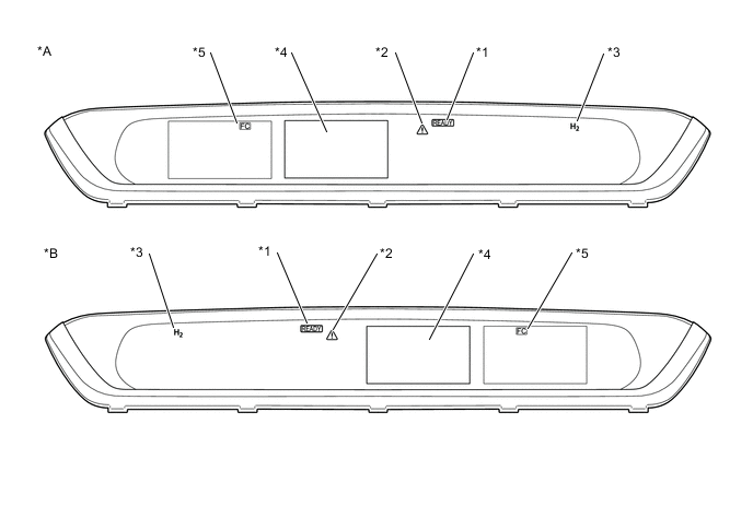
*A for LHD *B for RHD *1 READY Indicator *2 Master Warning Light *3 Hydrogen Leak Warning Light *4 Multi-information Display *5 Power restriction Indicator - - -
-
2 TRIP DETECTION LOGIC
-
When a malfunction is first detected, the malfunction is temporarily stored in the FC control ECU memory (1st trip). If the same malfunction is detected during the next drive cycle, the master warning light is illuminated (2nd trip).
-
-
FREEZE FRAME DATA
-
The FC control ECU records vehicle and driving condition information as freeze frame data the moment a DTC is stored. When troubleshooting, freeze frame data can be helpful in determining whether the vehicle was moving or stationary, whether the FC system was warmed up or not, as well as other data recorded at the time of a malfunction.
-
-
AUXILIARY BATTERY VOLTAGE
-
If voltage is below 11 V, recharge or replace the auxiliary battery.
Note
After turning the power switch off, waiting time may be required before disconnecting the cable from the negative (-) auxiliary battery terminal. Therefore, make sure to read the disconnecting the cable from the negative (-) auxiliary battery terminal notices before proceeding with work.
-
-
DIAGNOSTIC PRIORITY ORDER AND RELATED GTS CUSTOM LISTS
Diagnostic priority order and related GTS custom lists DTC No. Detection Item Order of Priority GTS Custom List*1 1 2 3 4 5 6 Microcomputer Malfunction Power Source Circuit Malfunction Communication System Malfunction Sensor and Actuator Circuit Malfunction System Malfunction FC stack malfunction P0100-450 Mass Air Flow Circuit - - - ○ - - - P0101-450 Mass Air Flow Circuit Range/Performance - - - - ○ - 2 P0112-450 Intake Air Temperature Circuit Low Input - - - ○ - - - P0113-450 Intake Air Temperature Circuit High Input - - - ○ - - - P0560-117 System Voltage - ○ - - - - - P060B-134 Internal Control Module A/D Processing Performance ○ - - - - - - P060B-135 Internal Control Module A/D Processing Performance ○ - - - - - - P060B-570 Internal Control Module A/D Processing Performance ○ - - - - - - P1D01-450 FCDC Control Module Requested MIL Illumination - - - - - - - P1D24-450 Hydrogen Pump Speed Control Performance - - - ○ - - 6 P1D27-450 FC Stack Coolant Temperature Sensor (Radiator Outlet) Circuit Low - - - ○ - - - P1D28-450 FC Stack Coolant Temperature Sensor (Radiator Outlet) Circuit High - - - ○ - - - P1D2C-450 FC Stack Coolant Temperature Sensor (FC Stack Outlet) Circuit Low - - - ○ - - - P1D2D-450 FC Stack Coolant Temperature Sensor (FC Stack Outlet) Circuit High - - - ○ - - - P1D2F-450 FC Water Pump Speed Control Performance - - - ○ - - 3 P1D3F-450 FC Stack Voltage Low - - - - - ○ 5 P1D5F-450 Lost Communication with Cell Monitor - - ○ - - - 5 P1D7F-450 Air Compressor Speed Control Performance - - - ○ - - 2 P1D83-450 Hydrogen Pump Inverter Performance - - - - ○ - 6 P1D84-450 Lost Communication with Hydrogen Pump Inverter - - ○ - - - - P1D87-450 Hydrogen Pump Motor Temperature Sensor Circuit Low - - - ○ - - - P1D88-450 Hydrogen Pump Motor Temperature Sensor Circuit High - - - ○ - - - P1D8C-450 FC Stack Air Temperature Sensor (FC Stack Inlet) Circuit Low - - - ○ - - - P1D8D-450 FC Stack Air Temperature Sensor (FC Stack Inlet) Circuit High - - - ○ - - - P1D91-450 Air Control System Performance - - - - ○ - 2 P1D92-450 FC Stack Air Pressure Sensor (FC Stack Inlet) Circuit Low - - - ○ - - - P1D93-450 FC Stack Air Pressure Sensor (FC Stack Inlet) Circuit High - - - ○ - - - P1D9C-450 Hydrogen Injector No. 1 Circuit Low - - - ○ - - - P1D9D-450 Hydrogen Injector No. 1 Circuit High - - - ○ - - - P1DA2-450 Hydrogen Injector No. 2 Circuit Low - - - ○ - - - P1DA3-450 Hydrogen Injector No. 2 Circuit High - - - ○ - - - P1DA7-450 Hydrogen Injector No. 3 Circuit Low - - - ○ - - - P1DA8-450 Hydrogen Injector No. 3 Circuit High - - - ○ - - - P1DAC-450 Exhaust Drainage Valve Circuit Low - - - ○ - - 1 P1DAD-450 Exhaust Drainage Valve Circuit High - - - ○ - - 1 P1DB1-450 High-range Hydrogen Pressure Sensor Correlation - - - ○ - - 4 P1DB2-450 High-range Hydrogen Pressure Sensor Circuit Low - - - ○ - - - P1DB3-450 High-range Hydrogen Pressure Sensor Circuit High - - - ○ - - - P1DB7-450 Medium-range Hydrogen Pressure Sensor Circuit Low - - - ○ - - - P1DB8-450 Medium-range Hydrogen Pressure Sensor Circuit High - - - ○ - - - P1DBC-450 Low-range Hydrogen Pressure Sensor Circuit Low - - - ○ - - - P1DBD-450 Low-range Hydrogen Pressure Sensor Circuit High - - - ○ - - - P1DC0-450 Low-range Hydrogen Pressure Too Low - - - - ○ - 1 P1DC1-450 Low-range Hydrogen Pressure Too High - - - - ○ - 1 P1DC3-450 Medium-range Hydrogen Pressure Too High - - - - ○ - 1 P1DC5-450 Air Pressure Too High - - - - ○ - 2 P1DC8-450 FC Water Pump Inverter Performance - - - - ○ - 3 P1DC9-450 Lost Communication with FC Water Pump Inverter - - ○ - - - 3 P1DCC-450 Motor Room Side Hydrogen Detector Circuit Low - - - ○ - - - P1DCD-450 Motor Room Side Hydrogen Detector Circuit High - - - ○ - - - P1DCF-450 Cell Monitor Performance ○ ○ - - - - 5 P1DD2-450 Tank Side Hydrogen Detector Circuit Low - - - ○ - - - P1DD3-450 Tank Side Hydrogen Detector Circuit High - - - ○ - - - P1DD5-450 Radiator Rotary Valve Circuit - - - ○ - - - P1DE4-450 FC Coolant Water Temperature Malfunction - - - - ○ - 3 P1DE6-450 Hydrogen Tank Temperature Sensor Correlation - - - ○ - - 4 P1DE7-450 Hydrogen Tank No. 1 Temperature Sensor Circuit Low - - - ○ - - - P1DE8-450 Hydrogen Tank No. 1 Temperature Sensor Circuit High - - - ○ - - - P1DEC-450 Hydrogen Tank No. 2 Temperature Sensor Circuit Low - - - ○ - - - P1DED-450 Hydrogen Tank No. 2 Temperature Sensor Circuit High - - - ○ - - - P1DEF-450 FC Stack Performance - - - - - ○ 5 P1DF2-450 Hydrogen Pump Inverter Drive Signal Stuck ON - - ○ - - - 6 P1DF3-450 Hydrogen Pump Inverter Drive Signal Stuck OFF - - ○ - - - 6 P1DF7-450 FC Water Pump Inverter Drive Signal Stuck ON - - ○ - - - 3 P1DF8-450 FC Water Pump Inverter Drive Signal Stuck OFF - - ○ - - - 3 P1DFC-450 Hydrogen Filling System High Pressure Sensor Circuit Low - - - ○ - - - P1DFD-450 Hydrogen Filling System High Pressure Sensor Circuit High - - - ○ - - - P1E02-450 Tank Shut Valve1 Circuit Low - - - ○ - - - P1E03-450 Tank Shut Valve1 Circuit High - - - ○ - - - P1E12-450 Tank Shut Valve2 Circuit Low - - - ○ - - - P1E13-450 Tank Shut Valve2 Circuit High - - - ○ - - - P1E19-450 Infrared Transmitter Circuit - - ○ - - - 4 P1E22-450 Air Pressure Regulating Valve Phase A Circuit Low - - - ○ - - - P1E23-450 Air Pressure Regulating Valve Phase A Circuit High - - - ○ - - - P1E27-450 Air Pressure Regulating Valve Phase B Circuit Low - - - ○ - - - P1E28-450 Air Pressure Regulating Valve Phase B Circuit High - - - ○ - - - P1E2C-450 Air Shunt Valve Phase A Circuit Low - - - ○ - - - P1E2D-450 Air Shunt Valve Phase A Circuit High - - - ○ - - - P1E32-450 Air Shunt Valve Phase B Circuit Low - - - ○ - - - P1E33-450 Air Shunt Valve Phase B Circuit High - - - ○ - - - P1E36-450 Tank Shut Valve1 Stuck Open or Close - - - ○ - - 7 P1E38-450 Tank Shut Valve2 Stuck Open or Close - - - ○ - - 7 P1E40-450 Hydrogen Leak (Motor Room Side) - - - - ○ - 1 P1E41-450 Hydrogen Leak (Tank Side) - - - - ○ - 1 P1E42-450 Hydrogen Pressure Leak (Excessive Hydrogen Flow) - - - - ○ - 1 P1E43-450 Hydrogen Pressure Leak (High/Medium Pressure Area) - - - - ○ - 1 P1E44-450 Hydrogen Pressure Leak (Low Pressure Area) - - - - ○ - 1 P1E47-450 FC Stack Coolant Temperature Sensor (FC Stack Outlet / Radiator Outlet) Correlation - - - ○ - - 3 P1E48-450 Barometric Pressure Sensor / FC Stack Air Pressure Sensor (FC Stack Inlet) Correlation - - - ○ - - 2 P1E49-450 Mass Air Flow Temperature Sensor Correlation - - - ○ - - 2 P1E6B-450 Fuel Lid Interlock Stuck Closed - - - ○ - - 4 P2228-450 Barometric Pressure Sensor "A" Circuit Low ○ - - - - - - P2229-450 Barometric Pressure Sensor "A" Circuit High ○ - - - - - - U0164-450 Lost Communication with HVAC Control Module - - ○ - - - - U0293-450 Lost Communication with EV System - - ○ - - - - U1160-450 Lost Communication with FCDC System - - ○ - - - - U1162-450 Lost Communication with Hydrogen Filling System - - ○ - - - - *1: The GTS custom list numbers recorded in the table above are applicable for the chart below. By using custom lists, the Data Monitor items can be narrowed down to those applicable for each DTC.
Tech Tips
Custom lists are selected Data Monitor items that are relevant to applicable systems. When using the GTS to check the Data Monitor, by selecting custom lists, the Data Monitor items can be narrowed down to those related to each specific DTC.
List of GTS Custom List Items Custom list item No. Primary 1 Air System 2 Cooling System 3 Hydrogen Filling 4 FC Stack/Cell Monitor 5 Hydrogen Pump 6 Tank Shut Valve 7 Insulation Abnormal 8 Tech Tips
The "Example of Multiple DTCs being Output" below is only one example of a malfunction condition. Therefore, a determination should not be made based on this alone.
-
The system has lost communication with the FC water pump inverter while the vehicle is traveling.
-
DTCs are detected and the vehicle behavior is as follows.
- Detected DTCs
-
P1DC9-450 (Lost Communication with FC Water Pump Inverter): Communication system malfunction*
-
P1DE4-450 (FC Coolant Water Temperature Malfunction): System malfunction*
-
P1D2F-450 (FC Water Pump Speed Control Performance): Sensor and actuator circuit malfunction*
-
*: Check the priority level in the "DTC Order of Priority" chart above.
- Vehicle Behavior
-
FC system stopped (Mode enters EV drive mode, and travel distance will be limited)
-
The inspection order of priority is: Microcomputer circuit → power source circuit → communication circuit → sensor and actuator circuit → system circuit → FC stack malfunction. Therefore, check the repair procedure for P1DC9-450.
-
Follow the repair procedures and replace the FC water and hydrogen pump inverter assembly. Finish the repair.
Example of Multiple DTCs being Output:
It is possible to check only the specified malfunctioning parts without having to check irrelevant parts.
-