HYBRID BATTERY SYSTEM, Diagnostic DTC:P0A84-123
| DTC Code | DTC Name |
|---|---|
| P0A84-123 | Battery Pack Cooling Fan 1 Control Circuit Low |
DESCRIPTION
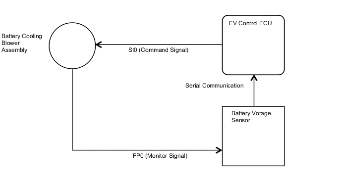
The battery cooling blower assembly speed is controlled by the EV control ECU. Power is supplied to battery cooling blower assembly when the MREL terminal of the EV control ECU turns on the IGCT relay. The EV control ECU sends command signals (SI) to battery cooling blower assembly to adjust the fan speed to an appropriate speed for the EV battery temperature. The frequency (FP) of battery cooling blower assembly is sent to the EV control ECU via the battery voltage sensor as a monitor signal using serial communication.
| DTC No. | Detection Item | DTC Detection Condition | Trouble Area | Warning Indicate |
|---|---|---|---|---|
| P0A84-123 | Battery Pack Cooling Fan 1 Control Circuit Low |
(1 trip detection logic) |
|
Master Warning Light: Comes on |
| DTC No. | Data List |
|---|---|
| P0A84-123 |
|
The following items can be helpful when performing repairs:
-
Temperature of Battery TB1 to TB3
-
Auxiliary Battery Voltage
Data List
| DTC No. | Active Test |
|---|---|
| P0A82-123 | Activate the Battery Cooling Fan |
Tech Tips
"Cooling Fan Frequency1" is detected when the battery cooling blower assembly is operating and its value changes in proportion to the battery cooling blower assembly speed.
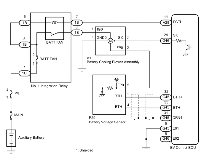
WIRING DIAGRAM
CAUTION / NOTICE / HINT
CAUTION:
-


Before the following operations are conducted, take precautions to prevent electric shock by turning the power switch off, wearing insulated gloves, and removing the service plug grips from both FC stack assembly and EV battery.
-
Inspecting the high-voltage system
-
Disconnecting the low voltage connector of the inverter with converter assembly
-
Disconnecting the low voltage connector of the EV battery
-
Disconnecting the low voltage connector of the FC stack assembly
-
Disconnecting the low voltage connector of the FC converter assembly
Tech Tips
No removal order is specified for the service plug grips of the FC stack assembly and EV battery.
-

After removing the service plug grip from the EV battery, put it in your pocket to prevent other technicians from accidentally reconnecting it while you are working on the high-voltage system. After removing the service grip from the FC stack assembly, store it in a safe location and use the "HIGH-VOLTAGE, DO NOT TOUCH" sign to notify other technicians that you are working on the high-voltage system.
-

*a Without waiting for 10 minutes After removal of the service plug grips of both FC stack assembly and EV battery, wait for at least 10 minutes before touching the high-voltage connectors and terminals. After waiting for 10 minutes, check the voltage at the terminals in the inspection point in the inverter with converter assembly. The voltage should be 0 V before beginning work.
Tech Tips
At least 10 minutes are necessary to discharge the high-voltage capacitors inside the inverter with converter assembly and FC stack assembly.
Note
-
After turning the power switch off, waiting time may be required before disconnecting the cable from the negative (-) auxiliary battery terminal. Therefore, make sure to read the disconnecting the cable from the negative (-) auxiliary battery terminal notices before proceeding with work.
-
When reinstalling the service plug grip to the FC stack assembly or the EV battery, slide the lever of the service plug until the letters "UNLOCK" are completely hidden, and insert it firmly.
-
When the vehicle is parked with the power switch off, if the FC control ECU judges that the FC stack temperature will go below 0°C (32°F), it activates the FC air compressor, hydrogen pump and FC cooling water pump for a maximum of 180 seconds and drains water from the FC stack assembly. When performing inspection or repairs with the power switch off (not on (IG) or on (READY)), disconnect the cable from the negative (-) auxiliary battery terminal before performing work (If the auxiliary battery voltage is needed to conduct inspection, warm up the FC system beforehand).
Tech Tips
-
As the battery cooling blower assembly speed is excessively low, there is a possibility of an open or short to ground in connected circuits, or motor locking.
-
After the repair, clear the DTCs and perform the following procedure to check that DTCs are not output.
-
Connect the GTS to the DLC3.
-
Turn the power switch on (IG).
-
Enter the following menus: Powertrain / EV / Active Test / Activate the Battery Cooling Fan.
-
Select fan mode 6 and operate the battery cooling blower assembly.
-
Operation of the battery cooling blower assembly can be confirmed by checking if air is sucked into the air intake port of the intake duct.
PROCEDURE
-
CHECK DTC OUTPUT (EV)
Result Result Proceed to P0AFC-123 is not output. A P0AFC-123 is also output. B
-
Connect the GTS to the DLC3.
-
Turn the power switch on (IG).
-
Enter the following menus: Powertrain / EV / Trouble Codes.
-
Check and record any hybrid control system DTCs, INF codes and freeze frame data.
-
Read output DTCs.
Powertrain > EV > Trouble CodesResult Result Proceed to P0AFC-123 is not output. A P0AFC-123 is also output. B -
Turn the power switch off.
-
Disconnect the GTS from the DLC3.
B 
GO TO DTC CHART (P0AFC-123) Click here
A 
-
-
PERFORM ACTIVE TEST USING GTS (ACTIVATE THE BATTERY COOLING FAN)
-
Connect the GTS to the DLC3.
-
Turn the power switch on (IG).
-
Enter the following menus: Powertrain / EV / Trouble Codes.
-
Clear DTCs and freeze frame data.
Note
When DTCs are cleared, freeze frame data and INF codes are also cleared.
Powertrain > EV > Clear DTCs -
Enter the following menus: Powertrain / EV / Active Test / Activate the Battery Cooling Fan.
Powertrain > EV > Active TestTester Display Measurement Item Control Range Restrict Condition Activate the Battery Cooling Fan Battery cooling blower assembly operation and blower volume can be checked. The battery cooling blower assembly can be turned off or operated in fan mode 1 through 6. -
Powertrain > EV > Active TestTester Display Activate the Battery Cooling Fan -
Select air volume mode 6 in the "Activate the Battery Cooling Fan" Active Test to operate the battery cooling blower assembly.
Note
If the Active Test cannot be performed, skip it and proceed to the next step to check the voltage. In accordance with fail-safe system operation, the EV control ECU sends a command to operate the battery cooling blower assembly.
-
Check that the battery cooling blower assembly operates and air is sucked into the inlet duct.
Tech Tips
The battery cooling blower assembly may not stop even when turning the cooling fan off in the "Activate the Battery Cooling Fan" Active Test. This is due to hybrid system control and is not a malfunction.
Standard Battery cooling blower assembly operates -
Turn the power switch off.
-
Disconnect the GTS from the DLC3.
Result Proceed to OK NG
NG 
CHECK FUSE (BATT FAN) Click here
OK
-
-
CHECK HARNESS AND CONNECTOR (BATTERY VOLTAGE SENSOR - BATTERY COOLING BLOWER ASSEMBLY)
CAUTION:
Be sure to wear insulated gloves.
-
Check that the service plug grip is not installed to FC stack assembly and EV battery.
Note
After removing the service plug grip, do not turn the power switch on (READY), unless instructed by the repair manual because this may cause a malfunction.
-
Remove the luggage compartment front trim cover.
-
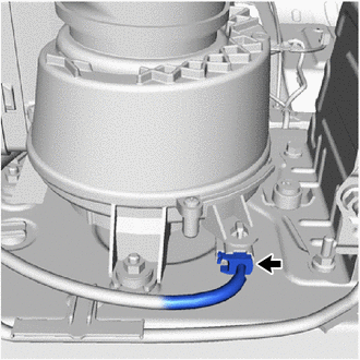
Disconnect the battery cooling blower assembly connector.
Note
Before disconnecting the connector, check that it is not loose or disconnected.
-
Disconnect the battery voltage sensor connector.
Note
-
Before disconnecting the connector, check that it is not loose or disconnected.
-
Check that each connector between the battery voltage sensor and battery cooling blower assembly is not loose or disconnected.
-
-
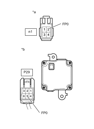
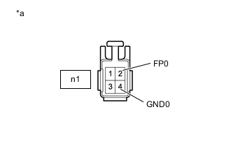
*a Front view of wire harness connector
(to Battery Cooling Blower Assembly)
*b Rear view of wire harness connector
(to Battery Voltage Sensor)
Measure the resistance according to the value(s) in the table below.
Standard Resistance Tester Connection Switch Condition Specified Condition P29-5 (FP0) - n1-2 (FP0) Power switch off Below 1 Ω n1-2 (FP0) - Body ground and other terminals Power switch off 10 kΩ or higher Note
When taking a measurement with a tester, do not apply excessive force to the tester probe to avoid damaging the holder.
-
Connect the cable to the negative (-) auxiliary battery terminal.
-
Turn the power switch on (IG).
-
Measure the voltage according to the value(s) in the table below.
Standard Voltage Tester Connection Switch Condition Specified Condition n1-2 (FP0) - Body ground Power switch on (IG) Below 1 V Note
-
Turning the power switch on (IG) with the service plug grip removed causes other DTCs to be stored. Clear the DTCs after performing this inspection.
-
If the power switch is turned on (IG) with the connectors disconnected, other DTCs will be stored. Be sure to clear the DTCs after the inspection.
-
When taking a measurement with a tester, do not apply excessive force to the tester probe to avoid damaging the holder.
Tech Tips
As there might be an intermittent malfunction, inspect the following items even if the measured voltage is as specified.
-
Check that each connector between the battery voltage sensor and battery cooling blower assembly is not loose or disconnected.
-
-
Turn the power switch off.
-
Disconnect the cable from the negative (-) auxiliary battery terminal.
-
Reconnect the battery voltage sensor connector.
-
Reconnect the battery cooling blower assembly connector.
-
Install the luggage compartment front trim cover.
Result Proceed to OK NG
NG
REPAIR OR REPLACE HARNESS OR CONNECTOR
OK
-
-
READ VALUE USING GTS (COOLING FAN FREQUENCY)
CAUTION:
Be sure to wear insulated gloves.
-
Check that the service plug grip is not installed to FC stack assembly and EV battery.
Note
After removing the service plug grip, do not turn the power switch on (READY), unless instructed by the repair manual because this may cause a malfunction.
-
Remove the luggage compartment front trim cover.
-
Connect the cable to the negative (-) auxiliary battery terminal.
-
Connect the GTS to the DLC3.
-
Turn the power switch on (IG).
-
Enter the following menus: Powertrain / EV / Trouble Codes.
-
Clear the DTCs and freeze frame data.
Note
When DTCs are cleared, freeze frame data and INF codes are also cleared.
Powertrain > EV > Clear DTCs -
Enter the following menus: Powertrain / EV / Active Test / Activate the Battery Cooling Fan.
Powertrain > EV > Active TestTester Display Measurement Item Control Range Restrict Condition Activate the Battery Cooling Fan Battery cooling blower assembly operation and blower volume can be checked. The battery cooling blower assembly can be turned off or operated in fan mode 1 through 6. -
Powertrain > EV > Active TestTester Display Activate the Battery Cooling Fan -
Enter the following menus: Powertrain / EV / Data List / Cooling Fan Frequency1.
Powertrain > EV > Data ListTester Display Cooling Fan Frequency 1 -
Select each air volume mode (1 to 6) in the "Activate the Battery Cooling Fan" Active Test to operate the battery cooling blower assembly.
Note
If the Active Test cannot be performed, skip it and proceed to the next step to check the frequency value. In accordance with fail-safe system operation, the EV control ECU sends a command to operate the battery cooling fan assembly.
-
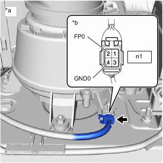
*a Component with harness connected
(Battery Cooling Blower Assembly)
*b Rear view of wire harness connector
(to Battery Cooling Blower Assembly)
While the cooling fan is operating, compare the value in the Data List (Cooling Fan Frequency 1) with the Frequency value that was actually measured with an oscilloscope at the battery cooling blower assembly connector.
Specified Condition Tester Connection Condition Specified Condition n1-2 (FP0) - n1-4 (GND0) Battery cooling blower assembly is operating. The value in the Data List (Cooling Fan Frequency1) and the actual measured value at the battery cooling blower assembly connector (No. 1) are 0 Hz. Note
-
Turning the power switch on (IG) with the service plug grip removed causes other DTCs to be stored. Clear the DTCs after performing this inspection.
-
When taking a measurement with a tester, do not apply excessive force to the tester probe to avoid damaging the holder.
Tech Tips
Compare the values in each air volume mode (1 to 6). If the Active Test cannot be performed, compare the values only in the current air volume mode.
-
-
Turn the power switch off.
-
Disconnect the GTS from the DLC3.
-
Disconnect the cable from the negative (-) auxiliary battery terminal.
-
Install the luggage compartment front trim cover.
Result Proceed to OK NG
NG
CHECK BATTERY VOLTAGE SENSOR (FREQUENCY) Click here
OK
-
-
CHECK BATTERY VOLTAGE SENSOR
CAUTION:
Be sure to wear insulated gloves.
-
Check that the service plug grip is not installed to FC stack assembly and EV battery.
Note
After removing the service plug grip, do not turn the power switch on (READY), unless instructed by the repair manual because this may cause a malfunction.
-
Remove the luggage compartment front trim cover.
-
Disconnect the battery cooling blower assembly connector.
-
Connect the cable to the negative (-) auxiliary battery terminal.
-
Turn the power switch on (IG).
-
*a Front view of wire harness connector
(to Battery Cooling Blower Assembly)
Measure the voltage according to the value(s) in the table below.
Standard Voltage Tester Connection Switch Condition Specified Condition n1-2 (FP0) - n1-4 (GND0) Power switch on (IG) 4.5 to 5.5 V Note
-
If the power switch is turned on (IG) with the service plug grip removed causes other DTCs will be stored. Be sure to clear the DTCs after the inspection.
-
If the power switch is turned on (IG) with the connectors disconnected, other DTCs will be stored. Be sure to clear the DTCs after the inspection.
-
When taking a measurement with a tester, do not apply excessive force to the tester probe to avoid damaging the holder.
-
-
Turn the power switch off.
-
Disconnect the cable from the negative (-) auxiliary battery terminal.
-
Reconnect the battery cooling blower assembly connector.
-
Install the luggage compartment front trim cover.
Result Proceed to OK NG
OK
REPLACE BATTERY COOLING BLOWER ASSEMBLY Click here
NG
REPLACE BATTERY VOLTAGE SENSOR Click here
-
-
CHECK BATTERY VOLTAGE SENSOR (FREQUENCY)
CAUTION:
Be sure to wear insulated gloves.
-
Check that the service plug grip is not installed to FC stack assembly and EV battery.
Note
After removing the service plug grip, do not turn the power switch on (READY), unless instructed by the repair manual because this may cause a malfunction.
-
Remove the luggage compartment front trim cover.
-
Connect the cable to the negative (-) auxiliary battery terminal.
-
Connect the GTS to the DLC3.
-
Turn the power switch on (IG).
-
Enter the following menus: Powertrain / EV / Trouble Codes.
-
Clear the DTCs and freeze frame data.
Note
When DTCs are cleared, freeze frame data and INF codes are also cleared.
Powertrain > EV > Clear DTCs -
Enter the following menus: Powertrain / EV / Active Test / Activate the Battery Cooling Fan.
Powertrain > EV > Active TestTester Display Measurement Item Control Range Restrict Condition Activate the Battery Cooling Fan Battery cooling blower assembly operation and blower volume can be checked. The battery cooling blower assembly can be turned off or operated in fan mode 1 through 6. -
Powertrain > EV > Active TestTester Display Activate the Battery Cooling Fan -
Enter the following menus: Powertrain / EV / Data List / Cooling Fan Frequency1.
Powertrain > EV > Data ListTester Display Cooling Fan Frequency 1 -
Select each air volume mode (1 to 6) in the "Activate the Battery Cooling Fan" Active Test to operate the battery cooling blower assembly.
Note
If the Active Test cannot be performed, skip it and proceed to the next step to check the frequency value. In accordance with fail-safe system operation, the EV control ECU sends a command to operate the battery cooling fan assembly.
-

*a Component with harness connected
(Battery Cooling Blower Assembly)
*b Rear view of wire harness connector
(to Battery Cooling Blower Assembly)
While the cooling fan is operating, compare the value in the Data List (Cooling Fan Frequency1) with the frequency value that was actually measured at the battery cooling blower assembly connector.
Specified Condition Tester Connection Condition Specified Condition n1-2 (FP0) - n1-4 (GND0) Battery cooling blower assembly is operating. Difference between the value in the Data List (Cooling Fan Frequency1) and the actual measurement value is 10% or less. Note
-
Turning the power switch on (IG) with the service plug grip removed causes other DTCs to be stored. Clear the DTCs after performing this inspection.
-
When taking a measurement with a tester, do not apply excessive force to the tester probe to avoid damaging the holder.
Tech Tips
Compare the values in each air volume mode (1 to 6). If the Active Test cannot be performed, compare the values only in the current air volume mode.
-
-
Turn the power switch off.
-
Disconnect the GTS from the DLC3.
-
Disconnect the cable from the negative (-) auxiliary battery terminal.
-
Install the luggage compartment front trim cover.
Result Proceed to OK NG
OK
REPLACE BATTERY COOLING BLOWER ASSEMBLY Click here
NG
REPLACE BATTERY VOLTAGE SENSOR Click here
-
-
CHECK FUSE (BATT FAN)
-
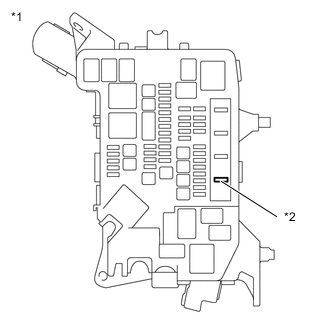
*1 Motor Compartment Relay Block *2 BATT FAN Fuse Remove the BATT FAN fuse from the motor compartment relay block.
-
Measure the resistance of the BATT FAN fuse.
Standard Resistance Tester Connection Condition Specified Condition BATT FAN fuse Always Below 1 Ω -
Install the BATT FAN fuse to the motor compartment relay block.
Result Proceed to OK NG
NG
CHECK HARNESS AND CONNECTOR (NO. 1 INTEGRATION RELAY - BATTERY COOLING BLOWER ASSEMBLY) Click here
OK
-
-
INSPECT NO. 1 INTEGRATION RELAY (BATT FAN)
-
Inspect the No. 1 integration relay.
Result Proceed to OK NG
NG
REPLACE NO. 1 INTEGRATION RELAY Click here
OK
-
-
CHECK BATTERY COOLING BLOWER ASSEMBLY (VOLTAGE)
CAUTION:
Be sure to wear insulated gloves.
-
Check that the service plug grip is not installed to FC stack assembly and EV battery.
Note
After removing the service plug grip, do not turn the power switch on (READY), unless instructed by the repair manual because this may cause a malfunction.
-
Remove the luggage compartment front trim cover.
-
Connect the cable to the negative (-) auxiliary battery terminal.
-
Turn the power switch on (IG).
-
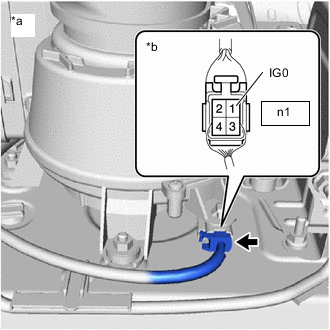
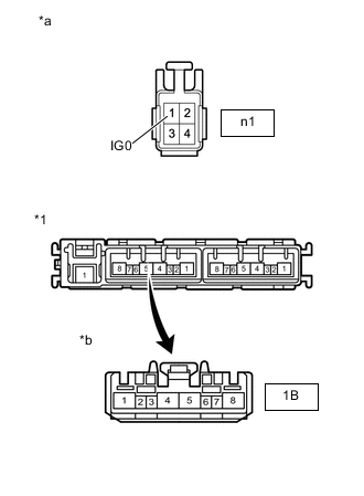
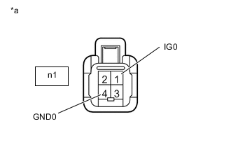
*a Component with harness connected
(Battery Cooling Blower Assembly)
*b Rear view of wire harness connector
(to Battery Cooling Blower Assembly)
Measure the voltage according to the value(s) in the table below.
Standard Voltage Tester Connection Switch Condition Specified Condition n1-1 (IG0) - Body ground Power switch on (IG) 11 to 14 V Note
-
Turning the power switch on (IG) with the service plug grip removed causes other DTCs to be stored. Clear the DTCs after performing this inspection.
-
When taking a measurement with a tester, do not apply excessive force to the tester probe to avoid damaging the holder.
Tech Tips
-
Perform this inspection with the battery cooling blower assembly connector connected.
-
As there might be an intermittent malfunction in the battery smart unit power source circuit, inspect the following even if the measured voltage is as specified:
-
Installation condition of fuse(s) (before removing fuse(s)) (IG circuit)
-
Fuse condition (before and after removing fuse(s)) (IG circuit)
-
Connection condition of connectors (IG circuit)
-
Wire harness condition (IG circuit)
-
Wire harness condition (GND circuit)
-
-
Turn the power switch off.
-
Disconnect the cable from the negative (-) auxiliary battery terminal.
-
Install the luggage compartment front trim cover.
Result Proceed to OK NG
NG
CHECK HARNESS AND CONNECTOR (EV CONTROL ECU - NO. 1 INTEGRATION RELAY) Click here
OK
-
-
CHECK HARNESS AND CONNECTOR (EV CONTROL ECU - BATTERY COOLING BLOWER ASSEMBLY)
CAUTION:
Be sure to wear insulated gloves.
-
Check that the service plug grip is not installed to FC stack assembly and EV battery.
Note
After removing the service plug grip, do not turn the power switch on (READY), unless instructed by the repair manual because this may cause a malfunction.
-
Remove the luggage compartment front trim cover.
-
Disconnect the battery cooling blower assembly connector.
Note
Before disconnecting the connector, check that it is not loose or disconnected.
-
Disconnect the EV control ECU connector.
Note
-
Before disconnecting the connector, check that it is not loose or disconnected.
-
Check that each connector between the EV control ECU and battery cooling blower assembly is not loose or disconnected.
-
-
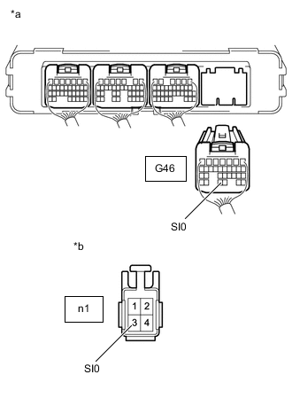
*a Rear view of wire harness connector
(to EV Control ECU)
*b Rear view of wire harness connector
(to Battery Cooling Blower Assembly)
Measure the resistance according to the value(s) in the table below.
Standard Resistance Tester Connection Switch Condition Specified Condition G46-29 (SI0) - n1-3 (SI0) Power switch off Below 1 Ω G46-29 (SI0) or n1-3 (SI0) - Body ground and other terminals Power switch off 10 kΩ or higher Note
When taking a measurement with a tester, do not apply excessive force to the tester probe to avoid damaging the holder.
-
Connect the cable to the negative (-) auxiliary battery terminal.
-
Turn the power switch on (IG).
-
Measure the voltage according to the value(s) in the table below.
Standard Voltage Tester Connection Switch Condition Specified Condition n1-3 (SI0) - Body ground Power switch on (IG) Below 1 V Note
-
Turning the power switch on (IG) with the service plug grip removed causes other DTCs to be stored. Clear the DTCs after performing this inspection.
-
If the power switch is turned on (IG) with the connectors disconnected, other DTCs will be stored. Be sure to clear the DTCs after the inspection.
-
When taking a measurement with a tester, do not apply excessive force to the tester probe to avoid damaging the holder.
Tech Tips
As there might be an intermittent malfunction, inspect the following items even if the measured voltage is as specified.
-
Check that each connector between the EV control ECU and battery cooling blower assembly is not loose or disconnected.
-
-
Turn the power switch off.
-
Disconnect the cable from the negative (-) auxiliary battery terminal.
-
Reconnect the battery cooling blower assembly connector.
-
Install the luggage compartment front trim cover.
-
Reconnect the EV control ECU connector.
Result Proceed to OK NG
NG
REPAIR OR REPLACE HARNESS OR CONNECTOR
OK
-
-
CHECK BATTERY COOLING BLOWER ASSEMBLY
CAUTION:
Be sure to wear insulated gloves.
-
Check that the service plug grip is not installed to FC stack assembly and EV battery
Note
After removing the service plug grip, do not turn the power switch on (READY), unless instructed by the repair manual because this may cause a malfunction.
-
Remove the luggage compartment front trim cover.
-
Connect the cable to the negative (-) auxiliary battery terminal.
-
Connect the GTS to the DLC3.
-
Turn the power switch on (IG).
-
Enter the following menus: Powertrain / EV / Trouble Codes.
-
Clear the DTCs and freeze frame data.
Note
When DTCs are cleared, freeze frame data and INF codes are also cleared.
Powertrain > EV > Clear DTCs -
Enter the following menus: Powertrain / EV / Active Test / Activate the Battery Cooling Fan.
Powertrain > EV > Active TestTester Display Measurement Item Control Range Restrict Condition Activate the Battery Cooling Fan Battery cooling blower assembly operation and blower volume can be checked. The battery cooling blower assembly can be turned off or operated in fan mode 1 through 6. -
Powertrain > EV > Active TestTester Display Activate the Battery Cooling Fan -
Select each air volume mode (1 to 6) in the "Activate the Battery Cooling Fan" Active Test to operate the battery cooling blower assembly.
Note
If the Active Test cannot be performed, skip it and proceed to the next step to check the frequency value. In accordance with fail-safe system operation, the EV control ECU sends a command to operate the battery cooling fan assembly.
-
Connect an oscilloscope between the battery cooling blower assembly terminals specified in the following table.
-
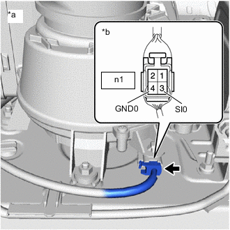
*a Component with harness connected
(Battery Cooling Blower Assembly)
*b Rear view of wire harness connector
(to Battery Cooling Blower Assembly)
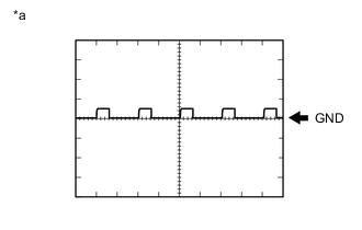
*a Waveform 1 Check the waveform.
Item Content Terminal n1-3 (SI0) - n1-4 (GND0) Equipment Setting 10 V/DIV., 1 ms./DIV. Condition Power switch on (IG), during Active Test Tech Tips
The waveform will vary depending on the content of the digital communication (digital signal).
Note
-
Turning the power switch on (IG) with the service plug grip removed causes other DTCs to be stored. Clear the DTCs after performing this inspection.
-
When taking a measurement with a tester, do not apply excessive force to the tester probe to avoid damaging the holder.
Result Result Proceed to Normal (Pulse is output as show in wveform 1) A No pulse output B -
-
Turn the power switch off.
-
Disconnect the cable from the negative (-) auxiliary battery terminal.
-
Install the luggage compartment front trim cover.
A
REPLACE BATTERY COOLING BLOWER ASSEMBLY Click here
B
REPLACE EV CONTROL ECU Click here
-
-
CHECK HARNESS AND CONNECTOR (EV CONTROL ECU - NO. 1 INTEGRATION RELAY)
-
Disconnect the No. 1 integration relay connector.
Note
Before disconnecting the connector, check that it is not loose or disconnected.
-
Disconnect the EV control ECU connector.
Note
Before disconnecting the connector, check that it is not loose or disconnected.
-
Measure the resistance according to the value(s) in the table below.
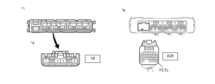
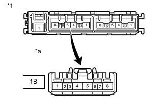
*1 No. 1 Integration Relay - - *a Front view of wire harness connector
(to No. 1 Integration Relay)
*b Rear view of wire harness connector
(to EV Control ECU)
Standard Resistance Tester Connection Switch Condition Specified Condition 1B-7 - A28-11 (FCTL) Power switch off Below 1 Ω Note
When taking a measurement with a tester, do not apply excessive force to the tester probe to avoid damaging the holder.
-
Connect the cable to the negative (-) auxiliary battery terminal.
-
Measure the voltage according to the value(s) in the table below.
Standard Voltage Tester Connection Switch Condition Specified Condition A28-11 (FCTL) - Body ground Power switch off Below 1 V Power switch on (IG) Note
-
If the power switch is turned on (IG) with the connectors disconnected, other DTCs will be stored. Be sure to clear the DTCs after the inspection.
-
When taking a measurement with a tester, do not apply excessive force to the tester probe to avoid damaging the holder.
-
-
Turn the power switch off.
-
Disconnect the cable from the negative (-) auxiliary battery terminal.
-
Reconnect the EV control ECU connector.
-
Reconnect the No. 1 integration relay connector.
Result Proceed to OK NG
NG
REPAIR OR REPLACE HARNESS OR CONNECTOR
OK
-
-
CHECK HARNESS AND CONNECTOR (EV CONTROL ECU - BODY GROUND)
-
Disconnect the EV control ECU connector.
Note
Before disconnecting the connector, check that it is not loose or disconnected.
-
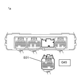
*a Rear view of wire harness connector
(to EV Control ECU)
Measure the resistance according to the value(s) in the table below.
Standard Resistance Tester Connection Switch Condition Specified Condition G45-5 (E01) - Body ground Power switch off Below 1 Ω Note
When taking a measurement with a tester, do not apply excessive force to the tester probe to avoid damaging the holder.
-
Reconnect the EV control ECU connector.
Result Proceed to OK NG
NG
REPAIR OR REPLACE HARNESS OR CONNECTOR
OK
-
-
CHECK HARNESS AND CONNECTOR (EV CONTROL ECU - BODY GROUND)
-
Disconnect the EV control ECU connector.
Note
Before disconnecting the connector, check that it is not loose or disconnected.
-
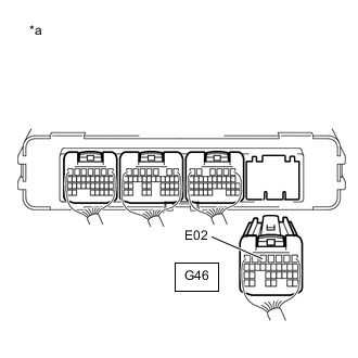
*a Rear view of wire harness connector
(to EV Control ECU)
Measure the resistance according to the value(s) in the table below.
Standard Resistance Tester Connection Switch Condition Specified Condition G46-5 (E02) - Body ground Power switch off Below 1 Ω Note
When taking a measurement with a tester, do not apply excessive force to the tester probe to avoid damaging the holder.
-
Reconnect the EV control ECU connector.
Result Proceed to OK NG
NG
REPAIR OR REPLACE HARNESS OR CONNECTOR
OK
-
-
CHECK HARNESS AND CONNECTOR (BATT FAN RELAY IGNITION COIL - BATT FAN RELAY CONTACT)
-
Disconnect the No. 1 integration relay connector.
Note
Before disconnecting the connector, check that it is not loose or disconnected.
-
*1 No. 1 Integration Relay *a Front view of wire harness connector
(to No. 1 Integration Relay)
Measure the resistance according to the value(s) in the table below.
Standard Resistance Tester Connection Switch Condition Specified Condition 1B-5 - 1B-6 Power switch off Below 1 Ω Note
When taking a measurement with a tester, do not apply excessive force to the tester probe to avoid damaging the holder.
-
Reconnect the No. 1 integration relay connector.
Result Proceed to OK NG
NG
REPAIR OR REPLACE HARNESS OR CONNECTOR
OK
-
-
CHECK HARNESS AND CONNECTOR (NO. 1 INTEGRATION RELAY - BATTERY COOLING BLOWER ASSEMBLY)
CAUTION:
Be sure to wear insulated gloves.
-
Check that the service plug grip is not installed to FC stack assembly and EV battery.
Note
After removing the service plug grip, do not turn the power switch on (READY), unless instructed by the repair manual because this may cause a malfunction.
-
Disconnect the No. 1 integration relay connector.
Note
Before disconnecting the connector, check that it is not loose or disconnected.
-
Remove the luggage compartment front trim cover.
-
Disconnect the battery cooling blower assembly connector.
Note
Before disconnecting the connector, check that it is not loose or disconnected.
-
*1 No. 1 Integration Relay *a Front view of wire harness connector
(to Battery Cooling Blower Assembly)
*b Front view of wire harness connector
(to No. 1 Integration Relay)
Measure the resistance according to the value(s) in the table below.
Standard Resistance Tester Connection Switch Condition Specified Condition n1-1 (IG0) - 1B-8 Power switch off Below 1 Ω Note
When taking a measurement with a tester, do not apply excessive force to the tester probe to avoid damaging the holder.
-
Reconnect the battery cooling blower assembly connector.
-
Install the luggage compartment front trim cover.
-
Install the No. 1 integration relay connector.
Result Proceed to OK NG
OK
REPLACE EV CONTROL ECU Click here
NG
REPAIR OR REPLACE HARNESS OR CONNECTOR
-
-
CHECK HARNESS AND CONNECTOR (NO. 1 INTEGRATION RELAY - BATTERY COOLING BLOWER ASSEMBLY)
CAUTION:
Be sure to wear insulated gloves.
-
Check that the service plug grip is not installed to FC stack assembly and EV battery.
Note
After removing the service plug grip, do not turn the power switch on (READY), unless instructed by the repair manual because this may cause a malfunction.
-
Disconnect the No. 1 integration relay connector.
Note
Before disconnecting the connector, check that it is not loose or disconnected.
-
Remove the luggage compartment front trim cover.
-
Disconnect the battery cooling blower assembly connector.
Note
Before disconnecting the connector, check that it is not loose or disconnected.
-
*1 No. 1 Integration Relay *a Front view of wire harness connector
(to Battery Cooling Blower Assembly)
*b Front view of wire harness connector
(to No. 1 Integration Relay)
Measure the resistance according to the value(s) in the table below.
Standard Resistance Tester Connection Switch Condition Specified Condition n1-1 (IG0) - Terminals other than 1B-8 and body ground Power switch off 10 kΩ or higher Note
When taking a measurement with a tester, do not apply excessive force to the tester probe to avoid damaging the holder.
-
Reconnect the battery cooling blower assembly connector.
-
Install the luggage compartment front trim cover.
-
Install the No. 1 integration relay connector.
Result Proceed to OK NG
NG
REPAIR OR REPLACE HARNESS OR CONNECTOR Click here
OK
-
-
CHECK BATTERY COOLING BLOWER ASSEMBLY
CAUTION:
Be sure to wear insulated gloves.
-
Check that the service plug grip is not installed to FC stack assembly and EV battery.
Note
After removing the service plug grip, do not turn the power switch on (READY), unless instructed by the repair manual because this may cause a malfunction.
-
Remove the luggage compartment front trim cover.
-
Disconnect the battery cooling blower assembly connector.
Note
Before disconnecting the connector, check that it is not loose or disconnected.
-
*a Component without harness connected
(Battery Cooling Blower Assembly)
Measure the resistance according to the value(s) in the table below.
Standard Resistance Tester Connection Switch Condition Specified Condition n1-1 (IG0) - n1-4 (GND0) and Body ground Power switch off 10 kΩ or higher Note
When taking a measurement with a tester, do not apply excessive force to the tester probe to avoid damaging the holder.
-
Reconnect the battery cooling blower assembly connector.
-
Install the luggage compartment front trim cover.
Result Proceed to OK NG
OK
REPLACE FUSE (BATT FAN)
NG
-
-
REPLACE BATTERY COOLING BLOWER ASSEMBLY
Result Proceed to NEXT
NEXT
REPLACE FUSE (BATT FAN)
-
REPAIR OR REPLACE HARNESS OR CONNECTOR
Result Proceed to NEXT
NEXT
REPLACE FUSE (BATT FAN)