HYBRID BATTERY SYSTEM, Diagnostic DTC:P0A9D-123, P0A9E-123, P0AC7-123, P0AC8-123, P0ACC-123, P0ACD-123
| DTC Code | DTC Name |
|---|---|
| P0A9D-123 | Battery Temperature Sensor "A" Circuit Low |
| P0A9E-123 | Battery Temperature Sensor "A" Circuit High |
| P0AC7-123 | Battery Temperature Sensor "B" Circuit Low |
| P0AC8-123 | Battery Temperature Sensor "B" Circuit High |
| P0ACC-123 | Battery Temperature Sensor "C" Circuit Low |
| P0ACD-123 | Battery Temperature Sensor "C" Circuit High |
DESCRIPTION
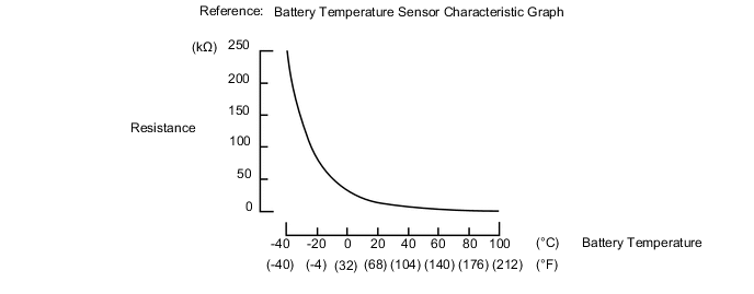
The battery temperature sensors are provided at 6 locations on the bottom of the EV battery. The resistance of the thermistor, which is built into each battery temperature sensor, varies in accordance with changes in the EV battery temperature. The lower the battery temperature, the higher the thermistor resistance. Conversely, the higher the temperature, the lower the resistance. The battery voltage sensor uses the battery temperature sensors to detect the EV battery temperature, and sends the detected value to the EV control ECU. Based on the results of this detection, the EV control ECU controls the blower fan. (The blower fan starts when the EV battery temperature rises above a predetermined level.)
| Temperature Sensor Identification Cross Reference Table | ||||||||||||
|---|---|---|---|---|---|---|---|---|---|---|---|---|
|
Tech Tips
For example, sensor A in the DTC title column is battery temperature sensor 0. This sensor is displayed as Temperature of Battery TB1 in the Data List.
| DTC No. | Detection Item | DTC Detection Condition | Trouble Area | Warning Indicate |
|---|---|---|---|---|
| P0A9D-123 | Battery Temperature Sensor "A" Circuit Low | The battery temperature sensor is malfunctioning, its output voltage is lower than the specified value (short circuit) and the detected temperature is higher than the specified value. (1 trip detection logic) |
|
Master Warning Light: Comes on |
| P0A9E-123 | Battery Temperature Sensor "A" Circuit High | The battery temperature sensor is malfunctioning, its output voltage is higher than the specified value (short to +B or open) and the detected temperature is lower than the specified value. (1 trip detection logic) |
|
Master Warning Light: Comes on |
| P0AC7-123 | Battery Temperature Sensor "B" Circuit Low | The battery temperature sensor is malfunctioning, its output voltage is lower than the specified value (short circuit) and the detected temperature is higher than the specified value. (1 trip detection logic) |
|
Master Warning Light: Comes on |
| P0AC8-123 | Battery Temperature Sensor "B" Circuit High | The battery temperature sensor is malfunctioning, its output voltage is higher than the specified value (short to +B or open) and the detected temperature is lower than the specified value. (1 trip detection logic) |
|
Master Warning Light: Comes on |
| P0ACC-123 | Battery Temperature Sensor "C" Circuit Low | The battery temperature sensor is malfunctioning, its output voltage is lower than the specified value (short circuit) and the detected temperature is higher than the specified value. (1 trip detection logic) |
|
Master Warning Light: Comes on |
| P0ACD-123 | Battery Temperature Sensor "C" Circuit High | The battery temperature sensor is malfunctioning, its output voltage is higher than the specified value (short to +B or open) and the detected temperature is lower than the specified value. (1 trip detection logic) |
|
Master Warning Light: Comes on |
Tech Tips
After checking for the above DTCs, check the hybrid system Data List item "Temperature of Battery" using the GTS.
| Temperature Displayed | Malfunction |
|---|---|
| Below -45°C (-49°F) | Open or +B short circuit |
| 95°C (203°F) or more | GND short circuit |
| DTC No. | Data List |
|---|---|
|
Temperature of Battery TB1 to TB3 |
Tech Tips
After leaving the vehicle for 1 day, the values of data monitor item "Temperature of Battery TB1 to TB3" should be equal to the outside temperature.
CAUTION / NOTICE / HINT
CAUTION:
-


Before the following operations are conducted, take precautions to prevent electric shock by turning the power switch off, wearing insulated gloves, and removing the service plug grips from both FC stack assembly and EV battery.
-
Inspecting the high-voltage system
-
Disconnecting the low voltage connector of the inverter with converter assembly
-
Disconnecting the low voltage connector of the EV battery
-
Disconnecting the low voltage connector of the FC stack assembly
-
Disconnecting the low voltage connector of the FC converter assembly
Tech Tips
No removal order is specified for the service plug grips of the FC stack assembly and EV battery.
-

After removing the service plug grip from the EV battery, put it in your pocket to prevent other technicians from accidentally reconnecting it while you are working on the high-voltage system. After removing the service grip from the FC stack assembly, store it in a safe location and use the "HIGH-VOLTAGE, DO NOT TOUCH" sign to notify other technicians that you are working on the high-voltage system.
-

*a Without waiting for 10 minutes After removal of the service plug grips of both FC stack assembly and EV battery, wait for at least 10 minutes before touching the high-voltage connectors and terminals. After waiting for 10 minutes, check the voltage at the terminals in the inspection point in the inverter with converter assembly. The voltage should be 0 V before beginning work.
Tech Tips
At least 10 minutes are necessary to discharge the high-voltage capacitors inside the inverter with converter assembly and FC stack assembly.
Note
-
After turning the power switch off, waiting time may be required before disconnecting the cable from the negative (-) auxiliary battery terminal. Therefore, make sure to read the disconnecting the cable from the negative (-) auxiliary battery terminal notices before proceeding with work.
-
When reinstalling the service plug grip to the FC stack assembly or the EV battery, slide the lever of the service plug until the letters "UNLOCK" are completely hidden, and insert it firmly.
-
When the vehicle is parked with the power switch off, if the FC control ECU judges that the FC stack temperature will go below 0°C (32°F), it activates the FC air compressor, hydrogen pump and FC cooling water pump for a maximum of 180 seconds and drains water from the FC stack assembly. When performing inspection or repairs with the power switch off (not on (IG) or on (READY)), disconnect the cable from the negative (-) auxiliary battery terminal before performing work (If the auxiliary battery voltage is needed to conduct inspection, warm up the FC system beforehand).
Tech Tips
-
After the repair, clear the DTCs and perform the following procedure to check that DTCs are not output.
-
Turn the power switch on (IG) and wait for 10 seconds or more.
-
When disposing of an EV battery, make sure to return it through an authorized collection agent who is capable of handling it safely. If the EV battery is returned via the manufacturer specified route, it will be returned properly and in a safe manner by an authorized collection agent.
PROCEDURE
-
CHECK DTC OUTPUT (EV)
Result Result Proceed to P0AFC-123 is not output. A P0AFC-123 is also output. B
-
Connect the GTS to the DLC3.
-
Turn the power switch on (IG).
-
Enter the following menus: Powertrain / EV / Trouble Codes.
-
Check and record any hybrid control system DTCs, INF codes and freeze frame data.
-
Read output DTCs.
Powertrain > EV > Trouble CodesResult Result Proceed to P0AFC-123 is not output. A P0AFC-123 is also output. B -
Turn the power switch off.
-
Disconnect the GTS from the DLC3.
B 
GO TO DTC CHART (P0AFC-123) Click here
A 
-
-
CHECK CONNECTOR CONNECTION CONDITION (BATTERY TEMPERATURE SENSOR)
CAUTION:
Be sure to wear insulated gloves.
-
Check that the service plug grip is not installed to FC stack assembly and EV battery.
Note
After removing the service plug grip, do not turn the power switch on (READY), unless instructed by the repair manual because this may cause a malfunction.
-
Remove the luggage compartment front trim cover.
-
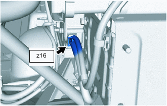
Check the connections of the battery voltage sensor connector.
OK The connectors are connected securely and there are no contact problems. -
Install the luggage compartment front trim cover.
Result Result OK NG
NG
CONNECT SECURELY
OK
-
-
CHECK EV BATTERY (BATTERY TEMPERATURE SENSOR)
Result Proceed to OK NG CAUTION:
Be sure to wear insulated gloves.
-
Check that the service plug grip is not installed to FC stack assembly and EV battery.
Note
After removing the service plug grip, do not turn the power switch on (READY), unless instructed by the repair manual because this may cause a malfunction.
-
Remove the luggage compartment front trim cover.
-
Remove the rear seatback assembly.
-
Disconnect the battery voltage sensor connector.
Note
Before disconnecting the connector, check that it is not loose or disconnected.
-
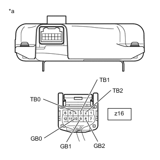
*a Rear view of wire harness connector
(to Battery Voltage Sensor)
Measure the resistance of the circuit for the malfunctioning sensor (battery temperature sensor 0 to 2).
Tester Connection Tester Connection Battery Temperature Sensor z16-4 (TB0) - z16-10 (GB0) 0 z16-3 (TB1) - z16-9 (GB1) 1 z16-2 (TB2) - z16-8 (GB2) 2 Note
When taking a measurement with a tester, do not apply excessive force to the tester probe to avoid damaging the holder.
Standard Resistance Thermistor Temperature Switch Condition Specified Condition 0°C (32°F) Power switch off 26.7 to 27.8 kΩ 25°C (77°F) Power switch off 9.9 to 10.1 kΩ 40°C (104°F) Power switch off 5.73 to 5.92 kΩ -
Measure the resistance according to the value(s) in the table below.
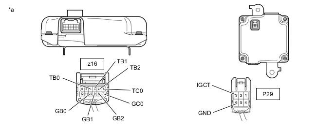
*a Rear view of wire harness connector
(to Battery Voltage Sensor)
- - Standard Resistance Tester Connection Switch Condition Specified Condition z16-4 (TB0) - P29-3 (IGCT) Power switch off 10 kΩ or higher z16-4 (TB0) - P29-6 (GND) Power switch off 10 kΩ or higher z16-10 (GB0) - P29-3 (IGCT) Power switch off 10 kΩ or higher z16-10 (GB0) - P29-6 (GND) Power switch off 10 kΩ or higher z16-3 (TB1) - P29-3 (IGCT) Power switch off 10 kΩ or higher z16-3 (TB1) - P29-6 (GND) Power switch off 10 kΩ or higher z16-9 (GB1) - P29-3 (IGCT) Power switch off 10 kΩ or higher z16-9 (GB1) - P29-6 (GND) Power switch off 10 kΩ or higher z16-2 (TB2) - P29-3 (IGCT) Power switch off 10 kΩ or higher z16-2 (TB2) - P29-6 (GND) Power switch off 10 kΩ or higher z16-8 (GB2) - P29-3 (IGCT) Power switch off 10 kΩ or higher z16-8 (GB2) - P29-6 (GND) Power switch off 10 kΩ or higher z16-1(TC0) - P29-3(IGCT) Power switch off 10 kΩ or higher z16-1(TC0) - P29-6(GND) Power switch off 10 kΩ or higher z16-7(GC0) - P29-3(IGCT) Power switch off 10 kΩ or higher z16-7(GC0) - P29-6(GND) Power switch off 10 kΩ or higher Note
When taking a measurement with a tester, do not apply excessive force to the tester probe to avoid damaging the holder.
-
Reconnect the battery voltage sensor connectors.
-
Install the rear seatback assembly.
-
Install the luggage compartment front trim cover.
Result Proceed to OK NG
OK
REPLACE BATTERY VOLTAGE SENSOR Click here
NG
-
-
CHECK HARNESS AND CONNECTOR (BATTERY TEMPERATURE SENSOR)
Result Proceed to OK NG CAUTION:
Be sure to wear insulated gloves.
-
Check that the service plug grip is not installed to FC stack assembly and EV battery.
Note
After removing the service plug grip, do not turn the power switch on (READY), unless instructed by the repair manual because this may cause a malfunction.
-
Remove the luggage compartment front trim cover.
-
Remove the rear seatback assembly.
-
Check the wire harness and connectors of the battery temperature sensor for abnormalities by sight and touch.
Specified Condition There are no open or short circuits in the wire harness and connectors. There are no short circuits to other wire harnesses. Tech Tips
As the battery harness is not available as a supply part, if the harness cannot be repaired, replace the EV battery.
-
Install the luggage compartment front trim cover.
Result Proceed to OK NG
OK
REPLACE EV BATTERY Click here
NG
REPAIR HARNESS OR CONNECTOR (BATTERY TEMPERATURE SENSOR)
-