HYBRID BATTERY SYSTEM, Diagnostic DTC:P0AC0-123
| DTC Code | DTC Name |
|---|---|
| P0AC0-123 | Battery Pack Current Sensor Circuit Range / Performance |
DESCRIPTION
Refer to the description for DTC P0ABF-123.
| DTC No. | Detection Item | DTC Detection Condition | Trouble Area | Warning Indicate |
|---|---|---|---|---|
| P0AC0-123 | Battery Pack Current Sensor Circuit Range / Performance | The offset value of the battery current sensor is excessively high, or the battery current sensor output is stuck. (1 trip detection logic) |
|
Master Warning Light: Comes on |
| DTC No. | Data List |
|---|---|
| P0AC0-123 | Battery Pack Current Value (IB Correction) |
CAUTION / NOTICE / HINT
CAUTION:
-


Before the following operations are conducted, take precautions to prevent electric shock by turning the power switch off, wearing insulated gloves, and removing the service plug grips from both FC stack assembly and EV battery.
-
Inspecting the high-voltage system
-
Disconnecting the low voltage connector of the inverter with converter assembly
-
Disconnecting the low voltage connector of the EV battery
-
Disconnecting the low voltage connector of the FC stack assembly
-
Disconnecting the low voltage connector of the FC converter assembly
Tech Tips
No removal order is specified for the service plug grips of the FC stack assembly and EV battery.
-

After removing the service plug grip from the EV battery, put it in your pocket to prevent other technicians from accidentally reconnecting it while you are working on the high-voltage system. After removing the service grip from the FC stack assembly, store it in a safe location and use the "HIGH-VOLTAGE, DO NOT TOUCH" sign to notify other technicians that you are working on the high-voltage system.
-

*a Without waiting for 10 minutes After removal of the service plug grips of both FC stack assembly and EV battery, wait for at least 10 minutes before touching the high-voltage connectors and terminals. After waiting for 10 minutes, check the voltage at the terminals in the inspection point in the inverter with converter assembly. The voltage should be 0 V before beginning work.
Tech Tips
At least 10 minutes are necessary to discharge the high-voltage capacitors inside the inverter with converter assembly and FC stack assembly.
Note
-
After turning the power switch off, waiting time may be required before disconnecting the cable from the negative (-) auxiliary battery terminal. Therefore, make sure to read the disconnecting the cable from the negative (-) auxiliary battery terminal notices before proceeding with work.
-
When reinstalling the service plug grip to the FC stack assembly or the EV battery, slide the lever of the service plug until the letters "UNLOCK" are completely hidden, and insert it firmly.
-
When the vehicle is parked with the power switch off, if the FC control ECU judges that the FC stack temperature will go below 0°C (32°F), it activates the FC air compressor, hydrogen pump and FC cooling water pump for a maximum of 180 seconds and drains water from the FC stack assembly. When performing inspection or repairs with the power switch off (not on (IG) or on (READY)), disconnect the cable from the negative (-) auxiliary battery terminal before performing work (If the auxiliary battery voltage is needed to conduct inspection, warm up the FC system beforehand).
Tech Tips
After the repair, clear the DTCs, perform the following operations, and check that no DTCs (including pending DTCs) are output.
-
Drive the vehicle on urban roads for approximately 10 minutes.
PROCEDURE
-
CHECK DTC OUTPUT (EV)
-
Connect the GTS to the DLC3.
-
Turn the power switch on (IG).
-
Enter the following menus: Powertrain / EV / Trouble Codes.
-
Check and record any hybrid control system DTCs, INF codes and freeze frame data.
-
Read output DTCs.
Powertrain > EV > Trouble CodesResult Result Proceed to Only DTC P0AC0-123 is output or DTC P0AC0-123 and DTCs other than those in the following table are output. A Any of the DTCs in the following table are output at the same time. B Relevant DTC P0A95-123 High Voltage Fuse P0ABF-123 Battery Pack Current Sensor Circuit P0AC1-123 Battery Pack Current Sensor Circuit Low P0AC2-123 Battery Pack Current Sensor Circuit High P0AFC-123 Battery Pack Sensor Module P0B3D-123, P0B42-123, P0B47-123, P0B4C-123, P0B51-123, P0B56-123, P0B5B-123, P0B60-123, P0B65-123, P0B6A-123, P0B6F-123, P0B74-123, P0B79-123, P0B7E-123, P0B83-123, P0B88-123, P0B8D-123, P0B92-123 Battery Voltage Sensor "A - R" Circuit Low -
Turn the power switch off.
-
Disconnect the GTS from the DLC3.
B 
GO TO DTC CHART (HYBRID BATTERY SYSTEM) Click here
A 
-
-
READ VALUE USING GTS
-
Connect the GTS to the DLC3.
-
Turn the power switch on (IG).
Note
Do not turn the power switch on (READY).
-
Enter the following menus: Powertrain / EV / Data List / Battery Block Voltage -V01 to V17.
Note
Select "Battery Block Voltage -V01 to V17" only. (Do not select any other Data List items.)
Powertrain > EV > Data ListTester Display Battery Block Voltage -V01 Battery Block Voltage -V02 Battery Block Voltage -V03 Battery Block Voltage -V04 Battery Block Voltage -V05 Battery Block Voltage -V06 Battery Block Voltage -V07 Battery Block Voltage -V08 Battery Block Voltage -V09 Battery Block Voltage -V10 Battery Block Voltage -V11 Battery Block Voltage -V12 Battery Block Voltage -V13 Battery Block Voltage -V14 Battery Block Voltage -V15 Battery Block Voltage -V16 Battery Block Voltage -V17 -
Check the voltage of each "Battery Block Voltage" of "Battery Block Voltage -V01 to V17" in the Data List with the power switch on (IG).
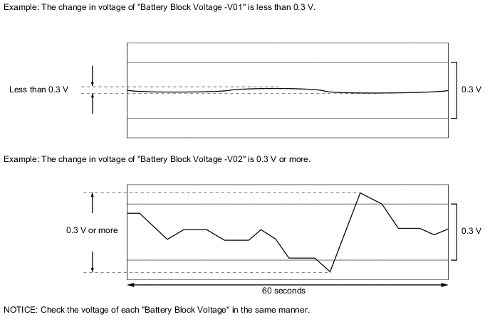
Specified Condition Any "Battery Block Voltage" changes by 0.3 V or more, 60 seconds after the power switch is turned on (IG). (The difference between the maximum and minimum voltage is 0.3 V or more.) Result Result Proceed to The change in voltage of any "Battery Block Voltage" is 0.3 V or more. A Other than above B -
Turn the power switch off.
-
Disconnect the GTS from the DLC3.
A
REPLACE BATTERY VOLTAGE SENSOR Click here
B
REPLACE EV BATTERY JUNCTION BLOCK ASSEMBLY Click here
-