HYBRID BATTERY SYSTEM, Diagnostic DTC:P0AFC-123
| DTC Code | DTC Name |
|---|---|
| P0AFC-123 | Battery Pack Sensor Module |
DESCRIPTION
If the battery voltage sensor detects an internal malfunction, it sends an error signal to the EV control ECU. When the EV control ECU receives the error signal from the battery voltage sensor, the ECU warns the driver and performs fail-safe control.
| DTC No. | Detection Item | DTC Detection Condition | Trouble Area | Warning Indicate |
|---|---|---|---|---|
| P0AFC-123 | Battery Pack Sensor Module | The EV control ECU receives an error signal from the battery voltage sensor. (1 trip detection logic) |
|
Master Warning Light: Comes on |
| DTC No. | Data List |
|---|---|
| P0AFC-123 | Auxiliary Battery Voltage |
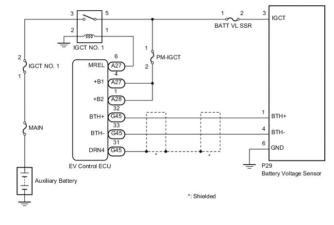
WIRING DIAGRAM
CAUTION / NOTICE / HINT
CAUTION:
-


Before the following operations are conducted, take precautions to prevent electric shock by turning the power switch off, wearing insulated gloves, and removing the service plug grips from both FC stack assembly and EV battery.
-
Inspecting the high-voltage system
-
Disconnecting the low voltage connector of the inverter with converter assembly
-
Disconnecting the low voltage connector of the EV battery
-
Disconnecting the low voltage connector of the FC stack assembly
-
Disconnecting the low voltage connector of the FC converter assembly
Tech Tips
No removal order is specified for the service plug grips of the FC stack assembly and EV battery.
-

After removing the service plug grip from the EV battery, put it in your pocket to prevent other technicians from accidentally reconnecting it while you are working on the high-voltage system. After removing the service grip from the FC stack assembly, store it in a safe location and use the "HIGH-VOLTAGE, DO NOT TOUCH" sign to notify other technicians that you are working on the high-voltage system.
-

*a Without waiting for 10 minutes After removal of the service plug grips of both FC stack assembly and EV battery, wait for at least 10 minutes before touching the high-voltage connectors and terminals. After waiting for 10 minutes, check the voltage at the terminals in the inspection point in the inverter with converter assembly. The voltage should be 0 V before beginning work.
Tech Tips
At least 10 minutes are necessary to discharge the high-voltage capacitors inside the inverter with converter assembly and FC stack assembly.
Note
-
After turning the power switch off, waiting time may be required before disconnecting the cable from the negative (-) auxiliary battery terminal. Therefore, make sure to read the disconnecting the cable from the negative (-) auxiliary battery terminal notices before proceeding with work.
-
When reinstalling the service plug grip to the FC stack assembly or the EV battery, slide the lever of the service plug until the letters "UNLOCK" are completely hidden, and insert it firmly.
-
When the vehicle is parked with the power switch off, if the FC control ECU judges that the FC stack temperature will go below 0°C (32°F), it activates the FC air compressor, hydrogen pump and FC cooling water pump for a maximum of 180 seconds and drains water from the FC stack assembly. When performing inspection or repairs with the power switch off (not on (IG) or on (READY)), disconnect the cable from the negative (-) auxiliary battery terminal before performing work (If the auxiliary battery voltage is needed to conduct inspection, warm up the FC system beforehand).
Tech Tips
-
After the repair, clear the DTCs and perform the following procedure to check that DTCs are not output.
-
Turn the power switch on (IG) and wait for 10 seconds or more.
-
When disposing of an EV battery, make sure to return it through an authorized collection agent who is capable of handling it safely. If the EV battery is returned via the manufacturer specified route, it will be returned properly and in a safe manner by an authorized collection agent.
PROCEDURE
-
CHECK HARNESS AND CONNECTOR (IGCT VOLTAGE)
CAUTION:
Be sure to wear insulated gloves.
-
Check that the service plug grip is not installed to FC stack assembly and EV battery.
Note
After removing the service plug grip, do not turn the power switch on (READY), unless instructed by the repair manual because this may cause a malfunction.
-
Remove the rear seatback assembly.
-
Connect the cable to the negative (-) auxiliary battery terminal.
-
Turn the power switch on (IG).
-
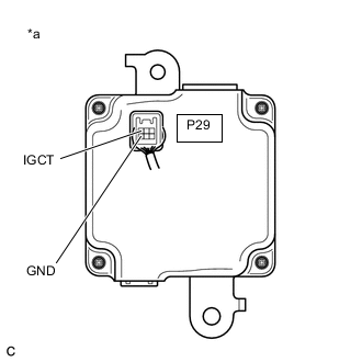
*a Component with harness connected
(Battery Voltage Sensor)
Measure the voltage according to the value(s) in the table below.
Standard Voltage Tester Connection Switch Condition Specified Condition P29-3 (IGCT) - P29-6 (GND) Power switch on (IG) 11 to 14 V Note
-
Turning the power switch on (IG) with the service plug grip removed causes other DTCs to be stored. Clear the DTCs after performing this inspection.
-
When taking a measurement with a tester, do not apply excessive force to the tester probe to avoid damaging the holder.
-
-
Turn the power switch off.
-
Disconnect the cable from the negative (-) auxiliary battery terminal.
-
Install the rear seatback assembly.
Result Proceed to OK NG
OK 
REPLACE BATTERY VOLTAGE SENSOR Click here
NG 
-
-
CHECK HARNESS AND CONNECTOR (BATTERY VOLTAGE SENSOR - BODY GROUND)
CAUTION:
Be sure to wear insulated gloves.
-
Check that the service plug grip is not installed to FC stack assembly and EV battery.
Note
After removing the service plug grip, do not turn the power switch on (READY), unless instructed by the repair manual because this may cause a malfunction.
-
Remove the rear seatback assembly.
-
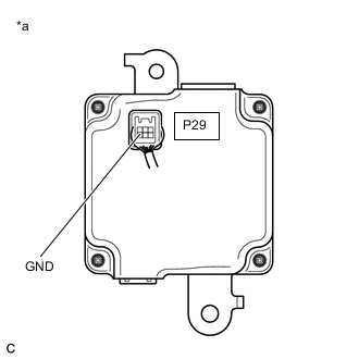
*a Component with harness connected
(Battery Voltage Sensor)
Measure the resistance according to the value(s) in the table below.
Standard Resistance Tester Connection Switch Condition Specified Condition P29-6 (GND) - Body ground Power switch off Below 1 Ω Note
When taking a measurement with a tester, do not apply excessive force to the tester probe to avoid damaging the holder.
-
Install the rear seatback assembly.
Result Proceed to OK NG
OK
REPAIR OR REPLACE HARNESS OR CONNECTOR (BATT VL SSR FUSE - BATTERY VOLTAGE SENSOR)
NG
REPAIR OR REPLACE HARNESS OR CONNECTOR (BATTERY VOLTAGE SENSOR - BODY GROUND)
-