HYBRID BATTERY SYSTEM, Diagnostic DTC:P0B3D-123, P0B42-123, P0B47-123, P0B4C-123, P0B51-123, P0B56-123, P0B5B-123, P0B60-123, P0B65-123, P0B6A-123, P0B6F-123, P0B74-123, P0B79-123, P0B7E-123, P0B83-123, P0B88-123, P0B8D-123, P0B92-123, P308A-123
| DTC Code | DTC Name |
|---|---|
| P0B3D-123 | Battery Voltage Sensor "A" Circuit Low |
| P0B42-123 | Battery Voltage Sensor "B" Circuit Low |
| P0B47-123 | Battery Voltage Sensor "C" Circuit Low |
| P0B4C-123 | Battery Voltage Sensor "D" Circuit Low |
| P0B51-123 | Battery Voltage Sensor "E" Circuit Low |
| P0B56-123 | Battery Voltage Sensor "F" Circuit Low |
| P0B5B-123 | Battery Voltage Sensor "G" Circuit Low |
| P0B60-123 | Battery Voltage Sensor "H" Circuit Low |
| P0B65-123 | Battery Voltage Sensor "I" Circuit Low |
| P0B6A-123 | Battery Voltage Sensor "J" Circuit Low |
| P0B6F-123 | Battery Voltage Sensor "K" Circuit Low |
| P0B74-123 | Battery Voltage Sensor "L" Circuit Low |
| P0B79-123 | Battery Voltage Sensor "M" Circuit Low |
| P0B7E-123 | Battery Voltage Sensor "N" Circuit Low |
| P0B83-123 | Battery Voltage Sensor "O" Circuit Low |
| P0B88-123 | Battery Voltage Sensor "P" Circuit Low |
| P0B8D-123 | Battery Voltage Sensor "Q" Circuit Low |
| P0B92-123 | Battery Voltage Sensor "R" Circuit Low |
| P308A-123 | Battery Voltage Sensor All Circuits Low |
DESCRIPTION
Refer to the description for DTC P0A80-123.
| DTC No. | Detection Item | DTC Detection Condition | Trouble Area | Warning Indicate |
|---|---|---|---|---|
| P0B3D-123 | Battery Voltage Sensor "A" Circuit Low | The battery block voltage detection line has a malfunction and any of the battery block voltages become lower than the specified value (open). (1 trip detection logic) |
|
Master Warning Light: Comes on |
| P0B42-123 | Battery Voltage Sensor "B" Circuit Low | The battery block voltage detection line has a malfunction and any of the battery block voltages become lower than the specified value (open). (1 trip detection logic) |
|
Master Warning Light: Comes on |
| P0B47-123 | Battery Voltage Sensor "C" Circuit Low | The battery block voltage detection line has a malfunction and any of the battery block voltages become lower than the specified value (open). (1 trip detection logic) |
|
Master Warning Light: Comes on |
| P0B4C-123 | Battery Voltage Sensor "D" Circuit Low | The battery block voltage detection line has a malfunction and any of the battery block voltages become lower than the specified value (open). (1 trip detection logic) |
|
Master Warning Light: Comes on |
| P0B51-123 | Battery Voltage Sensor "E" Circuit Low | The battery block voltage detection line has a malfunction and any of the battery block voltages become lower than the specified value (open). (1 trip detection logic) |
|
Master Warning Light: Comes on |
| P0B56-123 | Battery Voltage Sensor "F" Circuit Low | The battery block voltage detection line has a malfunction and any of the battery block voltages become lower than the specified value (open). (1 trip detection logic) |
|
Master Warning Light: Comes on |
| P0B5B-123 | Battery Voltage Sensor "G" Circuit Low | The battery block voltage detection line has a malfunction and any of the battery block voltages become lower than the specified value (open). (1 trip detection logic) |
|
Master Warning Light: Comes on |
| P0B60-123 | Battery Voltage Sensor "H" Circuit Low | The battery block voltage detection line has a malfunction and any of the battery block voltages become lower than the specified value (open). (1 trip detection logic) |
|
Master Warning Light: Comes on |
| P0B65-123 | Battery Voltage Sensor "I" Circuit Low | The battery block voltage detection line has a malfunction and any of the battery block voltages become lower than the specified value (open). (1 trip detection logic) |
|
Master Warning Light: Comes on |
| P0B6A-123 | Battery Voltage Sensor "J" Circuit Low | The battery block voltage detection line has a malfunction and any of the battery block voltages become lower than the specified value (open). (1 trip detection logic) |
|
Master Warning Light: Comes on |
| P0B6F-123 | Battery Voltage Sensor "K" Circuit Low | The battery block voltage detection line has a malfunction and any of the battery block voltages become lower than the specified value (open). (1 trip detection logic) |
|
Master Warning Light: Comes on |
| P0B74-123 | Battery Voltage Sensor "L" Circuit Low | The battery block voltage detection line has a malfunction and any of the battery block voltages become lower than the specified value (open). (1 trip detection logic) |
|
Master Warning Light: Comes on |
| P0B79-123 | Battery Voltage Sensor "M" Circuit Low | The battery block voltage detection line has a malfunction and any of the battery block voltages become lower than the specified value (open). (1 trip detection logic) |
|
Master Warning Light: Comes on |
| P0B7E-123 | Battery Voltage Sensor "N" Circuit Low | The battery block voltage detection line has a malfunction and any of the battery block voltages become lower than the specified value (open). (1 trip detection logic) |
|
Master Warning Light: Comes on |
| P0B83-123 | Battery Voltage Sensor "O" Circuit Low | The battery block voltage detection line has a malfunction and any of the battery block voltages become lower than the specified value (open). (1 trip detection logic) |
|
Master Warning Light: Comes on |
| P0B88-123 | Battery Voltage Sensor "P" Circuit Low | The battery block voltage detection line has a malfunction and any of the battery block voltages become lower than the specified value (open). (1 trip detection logic) |
|
Master Warning Light: Comes on |
| P0B8D-123 | Battery Voltage Sensor "Q" Circuit Low | The battery block voltage detection line has a malfunction and any of the battery block voltages become lower than the specified value (open). (1 trip detection logic) |
|
Master Warning Light: Comes on |
| P0B92-123 | Battery Voltage Sensor "R" Circuit Low | The battery block voltage detection line has a malfunction and any of the battery block voltages become lower than the specified value (open). (1 trip detection logic) |
|
Master Warning Light: Comes on |
| P308A-123 | Battery Voltage Sensor All Circuits Low | The battery block voltage detection line is open (all blocks) or all battery block voltages become lower than the specified value (possibility of open or loosely connected connector). (1 trip detection logic) |
|
Master Warning Light: Comes on |
Tech Tips
-
Values smaller than 2.0 V may not be shown in the Data List because a fail-safe value is substituted.
| DTC No. | Data List |
|---|---|
|
Battery Block Voltage -V01 to V17 |
| P308A-123 |
|
CAUTION / NOTICE / HINT
CAUTION:
-


Before the following operations are conducted, take precautions to prevent electric shock by turning the power switch off, wearing insulated gloves, and removing the service plug grips from both FC stack assembly and EV battery.
-
Inspecting the high-voltage system
-
Disconnecting the low voltage connector of the inverter with converter assembly
-
Disconnecting the low voltage connector of the EV battery
-
Disconnecting the low voltage connector of the FC stack assembly
-
Disconnecting the low voltage connector of the FC converter assembly
Tech Tips
No removal order is specified for the service plug grips of the FC stack assembly and EV battery.
-

After removing the service plug grip from the EV battery, put it in your pocket to prevent other technicians from accidentally reconnecting it while you are working on the high-voltage system. After removing the service grip from the FC stack assembly, store it in a safe location and use the "HIGH-VOLTAGE, DO NOT TOUCH" sign to notify other technicians that you are working on the high-voltage system.
-

*a Without waiting for 10 minutes After removal of the service plug grips of both FC stack assembly and EV battery, wait for at least 10 minutes before touching the high-voltage connectors and terminals. After waiting for 10 minutes, check the voltage at the terminals in the inspection point in the inverter with converter assembly. The voltage should be 0 V before beginning work.
Tech Tips
At least 10 minutes are necessary to discharge the high-voltage capacitors inside the inverter with converter assembly and FC stack assembly.
Note
-
After turning the power switch off, waiting time may be required before disconnecting the cable from the negative (-) auxiliary battery terminal. Therefore, make sure to read the disconnecting the cable from the negative (-) auxiliary battery terminal notices before proceeding with work.
-
When reinstalling the service plug grip to the FC stack assembly or the EV battery, slide the lever of the service plug until the letters "UNLOCK" are completely hidden, and insert it firmly.
-
When the vehicle is parked with the power switch off, if the FC control ECU judges that the FC stack temperature will go below 0°C (32°F), it activates the FC air compressor, hydrogen pump and FC cooling water pump for a maximum of 180 seconds and drains water from the FC stack assembly. When performing inspection or repairs with the power switch off (not on (IG) or on (READY)), disconnect the cable from the negative (-) auxiliary battery terminal before performing work (If the auxiliary battery voltage is needed to conduct inspection, warm up the FC system beforehand).
Tech Tips
-
After the repair, clear the DTCs and perform the following procedure to check that DTCs are not output.
-
Turn the power switch on (IG) and wait for 10 seconds or more.
-
When disposing of an EV battery, make sure to return it through an authorized collection agent who is capable of handling it safely. If the EV battery is returned via the manufacturer specified route, it will be returned properly and in a safe manner by an authorized collection agent.
PROCEDURE
-
CHECK DTC OUTPUT (EV)
-
Connect the GTS to the DLC3.
-
Turn the power switch on (IG).
-
Enter the following menus: Powertrain / EV / Trouble Codes.
-
Check and record any hybrid control system DTCs, INF codes and freeze frame data.
-
Read output DTCs.
Powertrain > EV > Trouble CodesResult Result Proceed to P0AFC-123 or P0A95-123 is not output. A P0AFC-123 or P0A95-123 is also output. B -
Turn the power switch off.
-
Disconnect the GTS from the DLC3.
B 
GO TO DTC CHART (HYBRID BATTERY SYSTEM) Click here
A 
-
-
CHECK CONNECTOR CONNECTION CONDITION
CAUTION:
Be sure to wear insulated gloves.
-
Check that the service plug grip is not installed to FC stack assembly and EV battery.
Note
After removing the service plug grip, do not turn the power switch on (READY), unless instructed by the repair manual because this may cause a malfunction.
-
Remove the No. 2 EV battery shield panel.
-
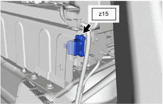
Check the connections of the battery voltage sensor connector.
OK The connectors are connected securely and there are no contact problems. -
Install the No. 2 EV battery shield panel.
Result Result OK NG
NG
CONNECT SECURELY
OK
-
-
REPLACE BATTERY VOLTAGE SENSOR
Result Proceed to NEXT
NEXT
-
CLEAR DTC (EV)
-
Connect the GTS to the DLC3.
-
Turn the power switch on (IG).
-
Enter the following menus: Powertrain / EV / Trouble Codes.
-
Clear the DTCs and freeze frame data.
Note
When DTCs are cleared, freeze frame data and INF codes are also cleared.
Powertrain > EV > Clear DTCs -
Turn the power switch off.
-
Disconnect the GTS from the DLC3.
-
Perform a reproduction test.
Result Proceed to NEXT
NEXT
-
-
RECONFIRM DTC OUTPUT (EV)
-
Turn the power switch off and wait for 3 minutes or more.
-
Connect the GTS to the DLC3.
-
Turn the power switch on (IG).
-
Enter the following menus: Powertrain / EV / Trouble Codes.
-
Read output DTCs.
Powertrain > EV > Trouble CodesResult Result Proceed to EV battery voltage sensor circuit DTCs for this diagnostic procedure are not output A EV battery voltage sensor circuit DTCs for this diagnostic procedure are output B Note
Turning the power switch on (IG) with the service plug grip removed causes other DTCs to be stored. Clear the DTCs after performing this inspection.
-
Turn the power switch off.
-
Disconnect the GTS from the DLC3.
A
RECOVERY TO NORMAL
B
REPLACE EV BATTERY Click here
-