HYBRID CONTROL SYSTEM Cooling System
DESCRIPTION
The cause of the malfunction may be the cooling system.
Check whether the grille is blocked, whether coolant is leaking, the EV radiator fan operating condition and whether coolant has frozen.
| Area | Inspection | Step |
|---|---|---|
| Grille blockage, coolant amount, coolant hoses, EV radiator fan | Check for overheating due to EV cooling system malfunction. | 1, 2, 3, 4 |
| Inverter coolant temperature sensor (built-in inverter) | Check for temperature sensor malfunction. | 5 |
| Coolant freezing check | Check freeze frame values to determine whether the EV coolant was frozen when the DTC was stored. | 6 |
SYSTEM DESCRIPTION
The inverter built inside the PCU and the inverter for the auxiliary pump convert the high-voltage direct current of the EV battery into alternating current for the drive motor, FC air compressor motor, FC water pump or hydrogen pump. The inverters generate heat during the conversion process. Therefore, the inverters are cooled by a special cooling system consisting of the EV water pump with motor assembly, the cooling fan, and a radiator. This cooling system is independent of the FC stack cooling system. The EV control ECU monitors the EV water pump with motor assembly, the cooling fan and cooling system, and detects malfunctions.
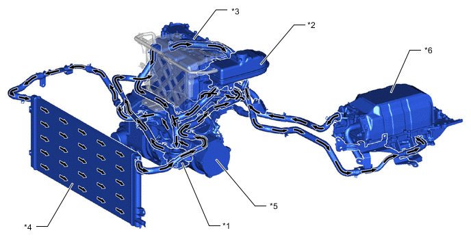
| *1 | EV Water Pump with Motor Assembly | *2 | Inverter Reserve Tank Assembly |
| *3 | Inverter with Converter Assembly | *4 | Radiator Assembly (EV) |
| *5 | FC Air Compressor with Motor Assembly | *6 | FC Converter Assembly |
CAUTION / NOTICE / HINT
This step is referenced from the procedures for each DTC.
If the inspection results below are normal, perform the next procedure for the referenced DTC.
CAUTION:
-


Before the following operations are conducted, take precautions to prevent electric shock by turning the power switch off, wearing insulated gloves, and removing the service plug grips from both FC stack assembly and EV battery.
-
Inspecting the high-voltage system
-
Disconnecting the low voltage connector of the inverter with converter assembly
-
Disconnecting the low voltage connector of the EV battery
-
Disconnecting the low voltage connector of the FC stack assembly
-
Disconnecting the low voltage connector of the FC converter assembly
Tech Tips
No removal order is specified for the service plug grips of the FC stack assembly and EV battery.
-

After removing the service plug grip from the EV battery, put it in your pocket to prevent other technicians from accidentally reconnecting it while you are working on the high-voltage system. After removing the service grip from the FC stack assembly, store it in a safe location and use the "HIGH-VOLTAGE, DO NOT TOUCH" sign to notify other technicians that you are working on the high-voltage system.
-

*a Without waiting for 10 minutes After removal of the service plug grips of both FC stack assembly and EV battery, wait for at least 10 minutes before touching the high-voltage connectors and terminals. After waiting for 10 minutes, check the voltage at the terminals in the inspection point in the inverter with converter assembly. The voltage should be 0 V before beginning work.
Tech Tips
At least 10 minutes are necessary to discharge the high-voltage capacitors inside the inverter with converter assembly and FC stack assembly.
Note
-
After turning the power switch off, waiting time may be required before disconnecting the cable from the negative (-) auxiliary battery terminal. Therefore, make sure to read the disconnecting the cable from the negative (-) auxiliary battery terminal notices before proceeding with work.
-
When reinstalling the service plug grip to the FC stack assembly or the EV battery, slide the lever of the service plug until the letters "UNLOCK" are completely hidden, and insert it firmly.
-
When the vehicle is parked with the power switch off, if the FC control ECU judges that the FC stack temperature will go below 0°C (32°F), it activates the FC air compressor, hydrogen pump and FC cooling water pump for a maximum of 180 seconds and drains water from the FC stack assembly. When performing inspection or repairs with the power switch off (not on (IG) or on (READY)), disconnect the cable from the negative (-) auxiliary battery terminal before performing work (If the auxiliary battery voltage is needed to conduct inspection, warm up the FC system beforehand).
PROCEDURE
-
CHECK VEHICLE CONDITION
-
Make sure that the front side of the radiator grille is not blocked with anything.
-
Ask the customer if the front side of the radiator grille was blocked with anything.
Result Result Proceed to Not blocked. A Is/was blocked. B Tech Tips
If the radiator grille is blocked, the inverter coolant temperature will increase and this DTC may be stored.
B 
IF EQUIPPED, EXPLAIN TO CUSTOMER THAT OPTIONAL COMPONENTS WILL BE REMOVED
A 
-
-
CHECK QUANTITY OF EV COOLANT
-
Check the EV coolant level in the inverter reserve tank.
-
Check for EV coolant leaks.
Result Result Proceed to No leaks are found and the EV coolant level in the inverter reserve tank assembly is above the low line. A No leaks are found and the EV coolant level in the inverter reserve tank assembly is below the low line. B EV coolant leaks are evident. C Tech Tips
-
After repairing the EV coolant leaks and adding coolant, perform the "Activate the Water Pump" Active Test (EV Active Test item) and the "Control the Electric Cooling Fan" Active Test (FC Active Test item) and make sure that there are no malfunctions.
-
The EV water pump with motor assembly will not malfunction due to coolant leaks.
-
B
ADD EV COOLANT
C
INSPECT FOR COOLANT LEAK AND ADD COOLANT
A
-
-
CHECK COOLANT HOSE
-
Check that the cooling system hoses are not kinked or clogged.
OK The cooling system hoses are not kinked or clogged. Result Proceed to OK NG
NG
REPAIR OR REPLACE COOLANT HOSE
OK
-
-
PERFORM ACTIVE TEST USING GTS (RADIATOR FAN1, RADIATOR FAN2)
-
Connect the GTS to the DLC3.
-
Turn the power switch on (IG).
-
Enter the following menus: Powertrain / FC / Active Test / Radiator Fan1, Radiator Fan2.
-
Perform the "Radiator Fan1, Radiator Fan2." Active Test.
Powertrain > FC > Active TestTester Display Radiator Fan1
Powertrain > FC > Active TestTester Display Radiator Fan2 OK The cooling fan rotates. -
Turn the power switch off.
Result Proceed to OK NG
NG
CHECK COOLING FAN SYSTEM Click here
OK
-
-
READ VALUE USING GTS (DATA LIST)
-
Turn the power switch off and leave the vehicle for at least 1 hour.
-
Connect the GTS to the DLC3.
-
Turn the power switch on (IG).
-
Enter the following menus: Powertrain / EV / Data List / FC Air Compressor Inverter Temperature, Drive Motor Inverter Temperature, Boosting Converter Temperature (Upper), Boosting Converter Temperature (Lower), Inverter Coolant Temperature.
Powertrain > EV > Data ListTester Display FC Air Compressor Inverter Temperature Drive Motor Inverter Temperature Boosting Converter Temperature (Upper) Boosting Converter Temperature (Lower) Inverter Coolant Temperature -
Read the Data List.
Result Result Proceed to Other than below. A "Inverter Coolant Temperature" value is higher than the displayed temperature of any other Data List item by 20°C (68°F) or more. B Tech Tips
The lower limit temperature that can be displayed for "Drive Motor Inverter Temperature", "Boosting Converter Temperature (Upper) and "FC Air Compressor Inverter Temperature" is 15°C (59°F). The lower limit temperature for "Inverter Coolant Temperature" is -40°C (-40°F). The "Inverter Coolant Temperature" value displayed on the GTS may be lower than the others, but this is not a malfunction.
-
Turn the power switch off.
B
REPLACE INVERTER WITH CONVERTER ASSEMBLY Click here
A
-
-
CHECK EV COOLANT (CHECK FOR CONDITIONS THAT MAY HAVE CAUSED FREEZING)
-
Connect the GTS to the DLC3.
-
Turn the power switch on (IG).
-
Enter the following menus: Powertrain / EV / Trouble Codes.
-
Read the freeze frame data item Ambient Temperature using the GTS.
Powertrain > EV > Trouble Codes -
Check if the freeze frame data item Ambient Temperature is below the freezing temperature of the EV coolant.
Result Result Proceed to Ambient Temperature value is above freezing temperature of the EV coolant. A Ambient Temperature value is below freezing temperature of the EV coolant. B Tech Tips
-
EV coolant (SLLC) with a 30% concentration freezes at -15°C (5°F) and EV coolant (SLLC) with a 50% concentration freezes at -35°C (-31°F).
-
If the EV coolant freezes in the EV radiator or EV water pump, the coolant temperature in the inverter with converter assembly rises because the EV coolant cannot circulate. As a result, a DTC may be stored.
-
A DTC is stored when the EV water pump impeller cannot rotate due to freezing of the EV coolant.
-
If DTCs are output due to freezing of the LLC, the problem symptom cannot be reproduced. Check the LLC replacement history and whether the LLC was frozen based on the ambient temperature when the DTCs were stored.
-
-
Turn the power switch off.
A
COOLING SYSTEM NORMAL (PERFORM NEXT STEP FOR REFERENCED DTC)
B
REPLACE EV COOLANT Click here
-