HYBRID CONTROL SYSTEM EV Battery High-voltage Line Circuit
CONTENTS
The cause of the malfunction may be the EV battery high-voltage line circuit.
Check the continuity in the high-voltage line from the EV battery to the inverter.
Check the connection condition and for an open circuit in the frame wire from the service plug grip (for EV) and EV battery to the inverter and perform a function check of the system main relay.
| Area | Inspection | Step |
|---|---|---|
| High-voltage circuit from EV battery to inverter | Check connection condition and for open circuit. | 1, 2, 3, 6, 7, 8, 9, 10, 11 |
| Service plug grip (for EV) | Check connection condition and for open circuit. | 4, 5 |
| System Main Relay | Check operation condition as relay. | 12, 13 |
DESCRIPTION
The EV battery high voltage is supplied to the inverter via the system main relay operation.
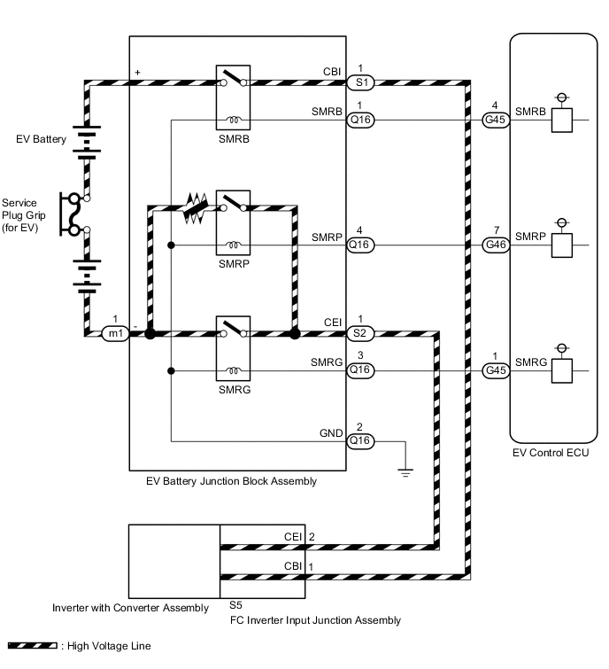
For high voltage wiring diagrams, refer to the system description.
WIRING DIAGRAM
CAUTION / NOTICE / HINT
This step is referenced from the procedures for each DTC.
If the inspection results below are normal, perform the next procedure for the referenced DTC.
CAUTION:
-


Before the following operations are conducted, take precautions to prevent electric shock by turning the power switch off, wearing insulated gloves, and removing the service plug grips from both FC stack assembly and EV battery.
-
Inspecting the high-voltage system
-
Disconnecting the low voltage connector of the inverter with converter assembly
-
Disconnecting the low voltage connector of the EV battery
-
Disconnecting the low voltage connector of the FC stack assembly
-
Disconnecting the low voltage connector of the FC converter assembly
Tech Tips
No removal order is specified for the service plug grips of the FC stack assembly and EV battery.
-

After removing the service plug grip from the EV battery, put it in your pocket to prevent other technicians from accidentally reconnecting it while you are working on the high-voltage system. After removing the service grip from the FC stack assembly, store it in a safe location and use the "HIGH-VOLTAGE, DO NOT TOUCH" sign to notify other technicians that you are working on the high-voltage system.
-

*a Without waiting for 10 minutes After removal of the service plug grips of both FC stack assembly and EV battery, wait for at least 10 minutes before touching the high-voltage connectors and terminals. After waiting for 10 minutes, check the voltage at the terminals in the inspection point in the inverter with converter assembly. The voltage should be 0 V before beginning work.
Tech Tips
At least 10 minutes are necessary to discharge the high-voltage capacitors inside the inverter with converter assembly and FC stack assembly.
Note
-
After turning the power switch off, waiting time may be required before disconnecting the cable from the negative (-) auxiliary battery terminal. Therefore, make sure to read the disconnecting the cable from the negative (-) auxiliary battery terminal notices before proceeding with work.
-
When reinstalling the service plug grip to the FC stack assembly or the EV battery, slide the lever of the service plug until the letters "UNLOCK" are completely hidden, and insert it firmly.
-
When the vehicle is parked with the power switch off, if the FC control ECU judges that the FC stack temperature will go below 0°C (32°F), it activates the FC air compressor, hydrogen pump and FC cooling water pump for a maximum of 180 seconds and drains water from the FC stack assembly. When performing inspection or repairs with the power switch off (not on (IG) or on (READY)), disconnect the cable from the negative (-) auxiliary battery terminal before performing work (If the auxiliary battery voltage is needed to conduct inspection, warm up the FC system beforehand).
PROCEDURE
-
CHECK FC INVERTER INPUT JUNCTION ASSEMBLY (CHECK CONNECTION CONDITION OF FRAME WIRE)
CAUTION:
Be sure to wear insulated gloves.
-
Check that the service plug grip is not installed to FC stack assembly and EV battery.
Note
After removing the service plug grip, do not turn the power switch on (READY), unless instructed by the repair manual because this may cause a malfunction.
-
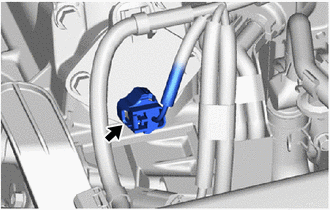
Disconnect the A45 FC inverter input junction cover connector.
-
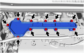
Remove the FC inverter input junction cover from the FC inverter input junction assembly.
-
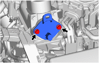
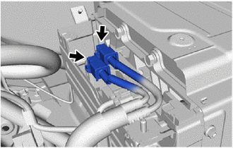
Check that the bolt for the frame wire is tightened to the specified torque, the frame wire is connected securely, and there are no contact problems.
Specified Condition 8.0 N*m (82 kgf*cm, 6 ft.*lbf) -
Disconnect the frame wire from the FC inverter input junction assembly.
-
Check for arc marks on the terminals of the frame wire.
Result Result Proceed to The terminals are connected securely and there are no contact problems. There are no arc marks. A There are arc marks. B The terminals are not connected securely and there is a contact problem. There are arc marks. There are no arc marks. C
B 
REPLACE MALFUNCTIONING PARTS
C
CONNECT SECURELY
A 
-
-
CHECK INVERTER WITH CONVERTER ASSEMBLY (CHECK CONNECTION CONDITION OF FC INVERTER INPUT JUNCTION ASSEMBLY)
CAUTION:
Be sure to wear insulated gloves.
-
Check that the service plug grip is not installed to FC stack assembly and EV battery.
Note
After removing the service plug grip, do not turn the power switch on (READY), unless instructed by the repair manual because this may cause a malfunction.
-
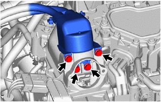
Remove the inverter terminal cover from the inverter with converter assembly.
-
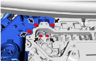
Check that the bolt for the FC inverter input junction assembly is tightened to the specified torque, the FC inverter input junction assembly is connected securely, and there are no contact problems.
Specified Condition T=8.0 N*m (82 kgf*cm, 6 ft.*lbf) -
Disconnect the FC inverter input junction assembly from the inverter with converter assembly.
-
Check for arc marks on the terminals of the FC inverter input junction assembly.
Result Result Proceed to The terminals are connected securely and there are no contact problems. There are no arc marks. A There are arc marks. B The terminals are not connected securely and there is a contact problem. There are arc marks. There are no arc marks. C
B
REPLACE MALFUNCTIONING PARTS
C
CONNECT SECURELY
A
-
-
CHECK FC INVERTER INPUT JUNCTION ASSEMBLY
CAUTION:
Be sure to wear insulated gloves.
-
Check that the service plug grip is not installed to FC stack assembly and EV battery.
Note
After removing the service plug grip, do not turn the power switch on (READY), unless instructed by the repair manual because this may cause a malfunction.
-
Measure the resistance according to the value(s) in the table below.
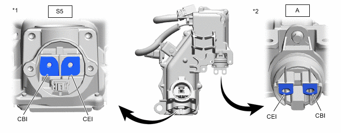
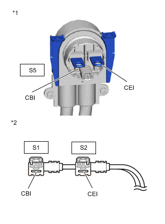
*1 FC Inverter Input Junction Assembly
(Frame Wire Side)
*2 FC Inverter Input Junction Assembly
(Inverter with Converter Assembly Side)
Standard Resistance Tester Connection Condition Specified Condition S5-1 (CBI) - A-2 (CBI) Power switch off Below 1 Ω S5-2 (CEI) - A-1 (CEI) Power switch off Below 1 Ω -
Connect the FC inverter input junction assembly to the inverter with converter assembly.
Result Proceed to OK NG
NG
REPLACE FC INVERTER INPUT JUNCTION ASSEMBLY Click here
OK
-
-
CHECK SERVICE PLUG GRIP (FOR EV)(CONNECTION CONDITION)
CAUTION:
Be sure to wear insulated gloves.
-
Visually check the connection of the service plug grip to the EV battery. Remove the service plug grip (for EV) and check for contamination.
OK Dirt or foreign matter has not entered the connectors, and there is no evidence of contamination. Result Proceed to OK NG
NG
REPLACE SERVICE PLUG GRIP (FOR EV) Click here
OK
-
-
INSPECT SERVICE PLUG GRIP (FOR EV)
-
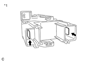
*1 Service Plug Grip (for EV) Measure the resistance according to the value(s) in the table below.
Standard Resistance Tester Connection Condition Specified Condition Service plug grip (for EV) terminals Always Below 1 Ω Result Proceed to OK NG
NG
REPLACE SERVICE PLUG GRIP (FOR EV) Click here
OK
-
-
CHECK EV BATTERY JUNCTION BLOCK ASSEMBLY (CHECK CONNECTION CONDITION OF FRAME WIRE)
CAUTION:
Be sure to wear insulated gloves.
-
Check that the service plug grip is not installed to FC stack assembly and EV battery.
Note
After removing the service plug grip, do not turn the power switch on (READY), unless instructed by the repair manual because this may cause a malfunction.
-
Remove the No. 4 EV battery shield panel.
-
Check the S1 and S2 connector connection condition between the frame wire and the EV battery junction block assembly.
-
Disconnect the S1 and S2 connector from the wire from the hybrid battery junction block assembly.
-
Check for arc marks on the terminals of the EV battery high voltage terminals.
Result Result Proceed to The terminals are connected securely and there are no contact problems. There are no arc marks. A There are arc marks. B The terminals are not connected securely and there is a contact problem. There are arc marks. There are no arc marks. C
B
REPLACE MALFUNCTIONING PARTS
C
CONNECT SECURELY
A
-
-
CHECK FRAME WIRE (FC INVERTER INPUT JUNCTION ASSEMBLY - EV BATTERY JUNCTION BLOCK ASSEMBLY)
CAUTION:
Be sure to wear insulated gloves.
-
Check that the service plug grip is not installed to FC stack assembly and EV battery.
Note
After removing the service plug grip, do not turn the power switch on (READY), unless instructed by the repair manual because this may cause a malfunction.
-
*1 Frame Wire
(FC Inverter Input Junction Assembly Side)
*2 Frame Wire
(EV Battery Junction Block Side)
Measure the resistance according to the value(s) in the table below.
Standard Resistance Tester Connection Condition Specified Condition S5-1 (CBI) - S1-1 (CBI) Power switch off Below 1 Ω S5-2 (CEI) - S2-1 (CEI) Power switch off Below 1 Ω Result Proceed to OK NG -
Connect the frame wire to the FC inverter input junction assembly and EV battery junction block.
NG
REPLACE FRAME WIRE Click here
OK
-
-
INSPECT EV BATTERY JUNCTION BLOCK ASSEMBLY (SMRB)
CAUTION:
Be sure to wear insulated gloves.
-
Check that the service plug grip is not installed to FC stack assembly and EV battery.
Note
After removing the service plug grip, do not turn the power switch on (READY), unless instructed by the repair manual because this may cause a malfunction.
-
Remove the EV battery junction block assembly.
-
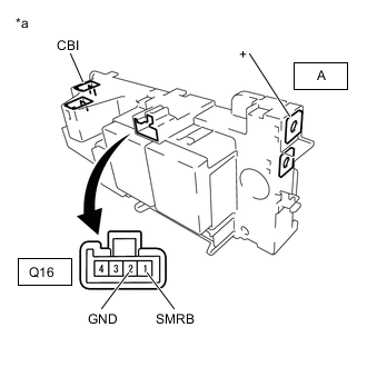
*a Component without harness connected
(EV Battery Junction Block Assembly)
Measure the resistance according to the value(s) in the table below.
Standard Resistance Tester Connection Condition Specified Condition A-1 (+) - CBI Auxiliary battery voltage applied between terminals Q16-1 (SMRB) and Q16-2 (GND) Below 1 Ω -
Measure the resistance according to the value(s) in the table below.
Standard Resistance Tester Connection Condition Specified Condition Q16-1 (SMRB) - Q16-2 (GND) -40 to 80°C (-40 to 176°F) 25.0 to 59.0 Ω -
Install the EV battery junction block assembly.
Result Proceed to OK NG
NG
REPLACE EV BATTERY JUNCTION BLOCK ASSEMBLY Click here
OK
-
-
INSPECT EV BATTERY JUNCTION BLOCK ASSEMBLY (SMRP)
CAUTION:
Be sure to wear insulated gloves.
-
Check that the service plug grip is not installed to FC stack assembly and EV battery.
Note
After removing the service plug grip, do not turn the power switch on (READY), unless instructed by the repair manual because this may cause a malfunction.
-
Remove the EV battery junction block assembly.
-
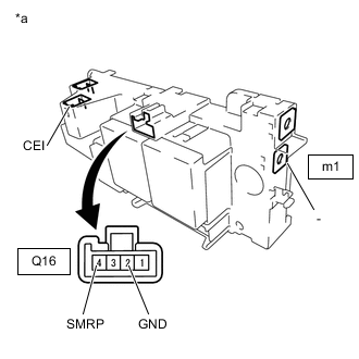
*a Component without harness connected
(EV Battery Junction Block Assembly)
Measure the resistance according to the value(s) in the table below.
Standard Resistance Tester Connection Condition Specified Condition m1-1 (-) - CEI Auxiliary battery voltage applied between terminals Q16-4 (SMRP) and Q16-2 (GND) 28.5 to 31.5 Ω -
Measure the resistance according to the value(s) in the table below.
Standard Resistance Tester Connection Condition Specified Condition Q16-4 (SMRP) - Q16-2 (GND) -40 to 80°C (-40 to 176°F) 112 to 274 Ω -
Install the EV battery junction block assembly.
Result Proceed to OK NG
OK
EV BATTERY HIGH-VOLTAGE LINE CIRCUIT NORMAL (PERFORM NEXT STEP FOR REFERENCED DTC)
NG
REPLACE EV BATTERY JUNCTION BLOCK ASSEMBLY Click here
-