HYBRID CONTROL SYSTEM Shut Down Signal Circuit
CONTENTS
The cause of the malfunction may be a shutdown signal.
Check whether there is a shutdown signal +B short circuit.
| Area | Inspection | Step |
|---|---|---|
| HSDN terminal voltage | Check that the HSDN terminal voltage decreases while READY OFF (IG ON). If the voltage is low, the shutdown signal circuit is normal. |
1 |
| EV control ECU, inverter | If there is a shutdown signal malfunction, check for whether there is a EV control ECU or inverter malfunction. | 2, 3 |
| FSDN, ISDN signal | Check FSDN or ISDN terminal for short to +B When a short to + B is has occurred on either terminal, the HSDN terminal voltage becomes high. |
4, 5 |
DESCRIPTION
Refer to the description for DTC P1D97-450.
Power supply to the motor is cut off due to a shutdown signal sent from the EV control ECU to the motor generator control ECU (MG ECU).
WIRING DIAGRAM
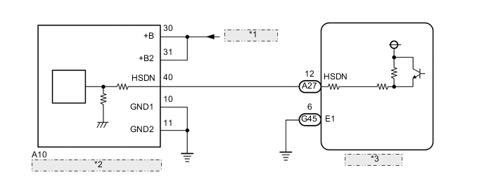
| *1 | from PCU Fuse |
| *2 | Inverter with Converter Assembly |
| *3 | EV Control ECU |
Refer to the wiring diagram for DTC P1D97-450.
CAUTION / NOTICE / HINT
This step is referenced from the procedures for each DTC.
If the inspection results below are normal, perform the next procedure for the referenced DTC.
CAUTION:
-


Before the following operations are conducted, take precautions to prevent electric shock by turning the power switch off, wearing insulated gloves, and removing the service plug grips from both FC stack assembly and EV battery.
-
Inspecting the high-voltage system
-
Disconnecting the low voltage connector of the inverter with converter assembly
-
Disconnecting the low voltage connector of the EV battery
-
Disconnecting the low voltage connector of the FC stack assembly
-
Disconnecting the low voltage connector of the FC converter assembly
Tech Tips
No removal order is specified for the service plug grips of the FC stack assembly and EV battery.
-

After removing the service plug grip from the EV battery, put it in your pocket to prevent other technicians from accidentally reconnecting it while you are working on the high-voltage system. After removing the service grip from the FC stack assembly, store it in a safe location and use the "HIGH-VOLTAGE, DO NOT TOUCH" sign to notify other technicians that you are working on the high-voltage system.
-

*a Without waiting for 10 minutes After removal of the service plug grips of both FC stack assembly and EV battery, wait for at least 10 minutes before touching the high-voltage connectors and terminals. After waiting for 10 minutes, check the voltage at the terminals in the inspection point in the inverter with converter assembly. The voltage should be 0 V before beginning work.
Tech Tips
At least 10 minutes are necessary to discharge the high-voltage capacitors inside the inverter with converter assembly and FC stack assembly.
Note
-
After turning the power switch off, waiting time may be required before disconnecting the cable from the negative (-) auxiliary battery terminal. Therefore, make sure to read the disconnecting the cable from the negative (-) auxiliary battery terminal notices before proceeding with work.
-
When reinstalling the service plug grip to the FC stack assembly or the EV battery, slide the lever of the service plug until the letters "UNLOCK" are completely hidden, and insert it firmly.
-
When the vehicle is parked with the power switch off, if the FC control ECU judges that the FC stack temperature will go below 0°C (32°F), it activates the FC air compressor, hydrogen pump and FC cooling water pump for a maximum of 180 seconds and drains water from the FC stack assembly. When performing inspection or repairs with the power switch off (not on (IG) or on (READY)), disconnect the cable from the negative (-) auxiliary battery terminal before performing work (If the auxiliary battery voltage is needed to conduct inspection, warm up the FC system beforehand).
PROCEDURE
-
CHECK EV CONTROL ECU
-
Turn the power switch on (IG).
-
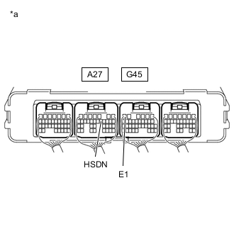
*a Component with harness connected
(EV Control ECU)
Measure the voltage according to the value(s) in the table below.
Standard Voltage Tester Connection Condition Specified Condition A27-12 (HSDN) - G45-6 (E1) Power switch on (IG) Below 4.5 V -
Turn the power switch off.
Result Proceed to OK NG
OK 
SHUT DOWN SIGNAL CIRCUIT NORMAL (PERFORM NEXT STEP FOR REFERENCED DTC)
NG 
-
-
CHECK HARNESS AND CONNECTOR (EV CONTROL ECU - INVERTER WITH CONVERTER ASSEMBLY)
CAUTION:
Be sure to wear insulated gloves.
-
Check that the service plug grip is not installed to FC stack assembly and EV battery.
Note
After removing the service plug grip, do not turn the power switch on (READY), unless instructed by the repair manual because this may cause a malfunction.
-
Disconnect the EV control ECU connector.
-
Disconnect the inverter with converter assembly connector.
-
Connect the cable to the negative (-) auxiliary battery terminal.
-
Turn the power switch on (IG).
-
Measure the voltage according to the value(s) in the table below.
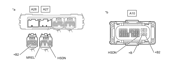
*a Rear view of wire harness connector
(to EV Control ECU)
*b Front view of wire harness connector
(to Inverter with Converter Assembly)
Standard Voltage Tester Connection Condition Specified Condition A10-40 (HSDN) or A27-12 (HSDN) - Body ground Power switch on (IG) Below 1 V Note
Turning the power switch on (IG) with the EV control ECU and inverter with converter assembly connector disconnected causes other DTCs to be stored. Clear the DTCs after performing this inspection.
-
Turn the power switch off.
-
Disconnect the cable from the negative (-) auxiliary battery terminal.
-
Measure the resistance according to the value(s) in the table below.
Standard Resistance Tester Connection Condition Specified Condition A10-40 (HSDN) - A10-30 (+B) Power switch off 10 kΩ or higher A10-40 (HSDN) - A10-31 (+B2) Power switch off 10 kΩ or higher A27-12 (HSDN) - A28-1 (+B2) Power switch off 10 kΩ or higher A27-12 (HSDN) - A27-6 (MREL) Power switch off 10 kΩ or higher -
Reconnect the inverter with converter assembly connector.
-
Reconnect the EV control ECU connector.
Result Proceed to OK NG
NG
REPAIR OR REPLACE HARNESS OR CONNECTOR
OK
-
-
CHECK INVERTER WITH CONVERTER ASSEMBLY
CAUTION:
Be sure to wear insulated gloves.
-
Check that the service plug grip is not installed to FC stack assembly and EV battery.
Note
After removing the service plug grip, do not turn the power switch on (READY), unless instructed by the repair manual because this may cause a malfunction.
-
Disconnect the inverter with converter assembly connector.
-
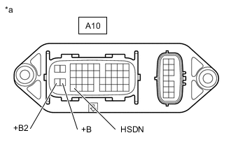
*a Component without harness connected
(Inverter with Converter Assembly)
Measure the resistance according to the value(s) in the table below.
Standard Resistance Tester Connection Condition Specified Condition A10-40 (HSDN) - A10-30 (+B) Power switch off 80 Ω or higher A10-40 (HSDN) - A10-31 (+B2) Power switch off 80 Ω or higher -
Reconnect the inverter with converter assembly connector.
Result Proceed to OK NG
NG
REPLACE INVERTER WITH CONVERTER ASSEMBLY Click here
OK
-
-
CHECK HARNESS AND CONNECTOR (EV CONTROL ECU - FC CONVERTER ASSEMBLY)
CAUTION:
Be sure to wear insulated gloves.
-
Check that the service plug grip is not installed to FC stack assembly and EV battery.
Note
After removing the service plug grip, do not turn the power switch on (READY), unless instructed by the repair manual because this may cause a malfunction.
-
Disconnect the EV Control ECU connector.
-
Disconnect the Ao2 FC converter assembly connector.
-
Connect the cable to the negative (-) auxiliary battery terminal.
-
Measure the voltage according to the value(s) in the table below.
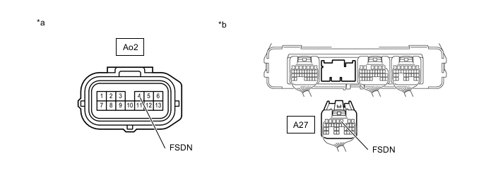
*a Front view of wire harness connector
(to FC Converter Assembly)
*b Rear view of wire harness connector
(to EV Control ECU)
Standard Voltage Tester Connection Condition Specified Condition Ao2-4 (FSDN) or A27-3 (FSDN) - Body ground Power switch on (IG) Below 1 V Note
Turning the power switch on (IG) with the EV control ECU and FC converter assembly connector disconnected causes other DTCs to be stored. Clear the DTCs after performing this inspection.
-
Turn the power switch off.
-
Disconnect the cable from the negative (-) auxiliary battery terminal.
-
Measure the resistance according to the value(s) in the table below.
Standard Resistance Tester Connection Condition Specified Condition Ao2-4 (FSDN) or A27-3 (FSDN) - Other terminals Power switch off 10 kΩ or higher -
Reconnect the FC converter assembly connector.
-
Reconnect the EV Control ECU connector.
Result Proceed to OK NG
NG
REPAIR OR REPLACE HARNESS AND CONNECTOR
OK
-
-
CHECK HARNESS AND CONNECTOR (EV CONTROL ECU CONNECTOR - FC CONVERTER ASSEMBLY)
CAUTION:
Be sure to wear insulated gloves.
-
Check that the service plug grip is not installed to FC stack assembly and EV battery.
Note
After removing the service plug grip, do not turn the power switch on (READY), unless instructed by the repair manual because this may cause a malfunction.
-
Disconnect the EV Control ECU connector.
-
Disconnect the Ao1 FC converter assembly connector.
-
Connect the cable to the negative (-) auxiliary battery terminal.
-
Turn the power switch on (IG).
-
Measure the voltage according to the value(s) in the table below.
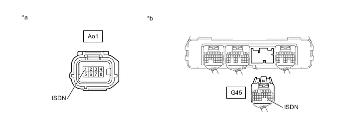
*a Rear view of wire harness connector
(to FC Converter Assembly)
*b Front view of wire harness connector
(to EV Control ECU)
Standard Voltage Tester Connection Condition Specified Condition Ao1-1 (ISDN) or G45-30 (ISDN) - Body ground Power switch on (IG) Below 1 V Note
Turning the power switch on (IG) with the EV control ECU and FC converter assembly connector disconnected causes other DTCs to be stored. Clear the DTCs after performing this inspection.
-
Turn the power switch off.
-
Disconnect the cable from the negative (-) auxiliary battery terminal.
-
Measure the resistance according to the value(s) in the table below.
Standard Resistance Tester Connection Condition Specified Condition G45-30 (ISDN) or Ao1-1 (ISDN) - Other terminals Power switch off 10 kΩ or higher -
Reconnect the FC converter assembly connector.
-
Reconnect the EV Control ECU connector.
Result Proceed to OK NG
NG
REPAIR OR REPLACE HARNESS OR CONNECTOR
OK
-
-
CHECK FC CONVERTER ASSEMBLY (CHECK FSDN TERMINAL FOR SHORT TO +B)
CAUTION:
Be sure to wear insulated gloves.
-
Check that the service plug grip is not installed to FC stack assembly and EV battery.
Note
After removing the service plug grip, do not turn the power switch on (READY), unless instructed by the repair manual because this may cause a malfunction.
-
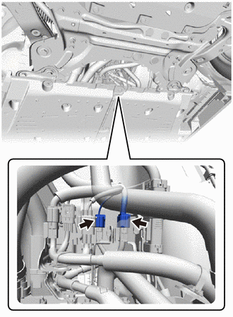
Disconnect the Ao1 and Ao2 FC converter assembly connector.
-
Measure the resistance according to the value(s) in the table below.
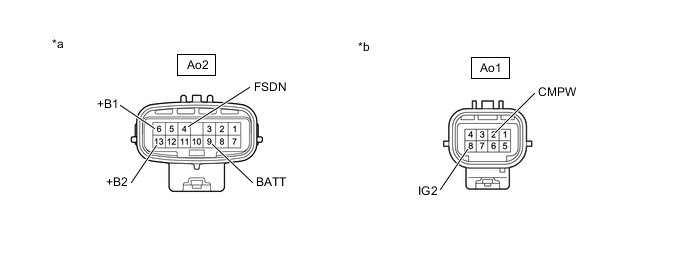
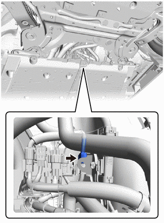
*a Component without harness connected
(FC Converter Assembly)
*b Component without harness connected
(FC Converter Assembly)
Standard Resistance Tester Connection Condition Specified Condition Ao2-4 (FSDN) - Ao2-6 (+B1) Power switch off 10 kΩ or higher Ao2-4 (FSDN) - Ao2-9 (BATT) Power switch off 10 kΩ or higher Ao2-4 (FSDN) - Ao2-13 (+B2) Power switch off 10 kΩ or higher Ao2-4 (FSDN) - Ao1-2 (CMPW) Power switch off 10 kΩ or higher Ao2-4 (FSDN) - Ao1-8 (IG2) Power switch off 10 kΩ or higher -
Reconnect the FC converter assembly connector.
Result Proceed to OK NG
NG
REPLACE FC CONVERTER ASSEMBLY Click here
OK
-
-
CHECK FC CONVERTER ASSEMBLY (CHECK ISDN TERMINAL FOR SHORT TO +B)
CAUTION:
Be sure to wear insulated gloves.
-
Check that the service plug grip is not installed to FC stack assembly and EV battery.
Note
After removing the service plug grip, do not turn the power switch on (READY), unless instructed by the repair manual because this may cause a malfunction.
-
Disconnect the Ao1 and Ao2 FC converter assembly connector.
-
Measure the resistance according to the value(s) in the table below.
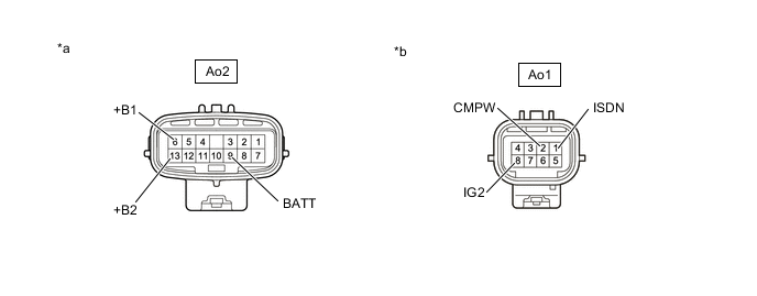
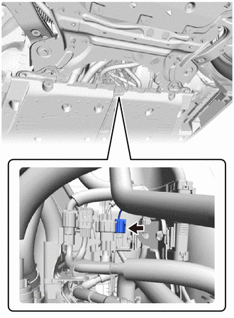
*a Component without harness connected
(FC Converter Assembly)
*b Component without harness connected
(FC Converter Assembly)
Standard Resistance Tester Connection Condition Specified Condition Ao1-1 (ISDN) - Ao2-6 (+B1) Power switch off 10 kΩ or higher Ao1-1 (ISDN) - Ao2-9 (BATT) Power switch off 10 kΩ or higher Ao1-1 (ISDN) - Ao2-13 (+B2) Power switch off 10 kΩ or higher Ao1-1 (ISDN) - Ao1-2 (CMPW) Power switch off 10 kΩ or higher Ao1-1 (ISDN) - Ao1-8 (IG2) Power switch off 10 kΩ or higher -
Reconnect the FC converter assembly connector.
Result Proceed to OK NG
OK
REPLACE EV CONTROL ECU Click here
NG
REPLACE FC CONVERTER ASSEMBLY Click here
-