HYBRID CONTROL SYSTEM, Diagnostic DTC:U1162-450
| DTC Code | DTC Name |
|---|---|
| U1162-450 | Lost Communication with Hydrogen Filling System |
DESCRIPTION
Refer to the description for DTC U1160-450.
| DTC No. | Detection Item | DTC Detection Condition | Trouble Area | Warning Indicate |
|---|---|---|---|---|
| U1162-450 | Lost Communication with Hydrogen Filling System | A CAN communication error between the hydrogen fuel control ECU and EV control ECU (CAN communication system malfunction) occurs. |
|
Master Warning Light: Comes on |
-
*1: w/ Diagnosis Recorder ECU
CAUTION / NOTICE / HINT
CAUTION:
-


Before the following operations are conducted, take precautions to prevent electric shock by turning the power switch off, wearing insulated gloves, and removing the service plug grips from both FC stack assembly and EV battery.
-
Inspecting the high-voltage system
-
Disconnecting the low voltage connector of the inverter with converter assembly
-
Disconnecting the low voltage connector of the EV battery
-
Disconnecting the low voltage connector of the FC stack assembly
-
Disconnecting the low voltage connector of the FC converter assembly
Tech Tips
No removal order is specified for the service plug grips of the FC stack assembly and EV battery.
-

After removing the service plug grip from the EV battery, put it in your pocket to prevent other technicians from accidentally reconnecting it while you are working on the high-voltage system. After removing the service grip from the FC stack assembly, store it in a safe location and use the "HIGH-VOLTAGE, DO NOT TOUCH" sign to notify other technicians that you are working on the high-voltage system.
-

*a Without waiting for 10 minutes After removal of the service plug grips of both FC stack assembly and EV battery, wait for at least 10 minutes before touching the high-voltage connectors and terminals. After waiting for 10 minutes, check the voltage at the terminals in the inspection point in the inverter with converter assembly. The voltage should be 0 V before beginning work.
Tech Tips
At least 10 minutes are necessary to discharge the high-voltage capacitors inside the inverter with converter assembly and FC stack assembly.
Note
-
After turning the power switch off, waiting time may be required before disconnecting the cable from the negative (-) auxiliary battery terminal. Therefore, make sure to read the disconnecting the cable from the negative (-) auxiliary battery terminal notices before proceeding with work.
-
When reinstalling the service plug grip to the FC stack assembly or the EV battery, slide the lever of the service plug until the letters "UNLOCK" are completely hidden, and insert it firmly.
-
When measuring the resistance of the CAN bus, turn the power switch off, wait for at least 1 minute without operating the key, operating any switches, or opening or closing any doors, then disconnect the auxiliary battery cable and wait again for at least 1 minute before measuring the resistance.
-
Inspect the fuses of circuits related to this system before performing the following procedure.
-
When the vehicle is parked with the power switch off, if the FC control ECU judges that the FC stack temperature will go below 0°C (32°F), it activates the FC air compressor, hydrogen pump and FC cooling water pump for a maximum of 180 seconds and drains water from the FC stack assembly. When performing inspection or repairs with the power switch off (not on (IG) or on (READY)), disconnect the cable from the negative (-) auxiliary battery terminal before performing work (If the auxiliary battery voltage is needed to conduct inspection, warm up the FC system beforehand).
Tech Tips
After the repair, clear the DTCs and perform the following procedure to check that DTCs are not output.
-
Turn the power switch on (IG) and wait for 2 minutes or more.
PROCEDURE
-
CHECK DTC OUTPUT (EV)
-
Connect the GTS to the DLC3.
-
Turn the power switch on (IG).
-
Enter the following menus: Powertrain : Powertrain / EV / Trouble Codes.
-
Check for DTCs.
Powertrain > EV > Trouble CodesResult Result Proceed to P0A1D-148 is not output. A P0A1D-148 is output. B Tech Tips
U1162-450 may be output as a result of the malfunction indicated by the DTCs above.
-
Turn the power switch off.
B 
GO TO DTC CHART (P0A1D-148) Click here
A 
-
-
CHECK CAN BUS MAIN WIRE (OPEN OR SHORT IN FC LOCAL BUS)
-
Disconnect the cable from the negative (-) auxiliary battery terminal.
-
Disconnect the EV control ECU connector.
-
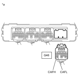
*a Front view of wire harness connector
(to EV Control ECU)
Measure the resistance according to the value(s) in the table below.
Standard Resistance Tester Connection Condition Specified Condition G46-31 (CAFH) - G46-30 (CAFL) Cable disconnected from negative (-) auxiliary battery terminal 54 to 69 Ω G46-31 (CAFH) or G46-30 (CAFL) - Body ground and other terminals Cable disconnected from negative (-) auxiliary battery terminal 10 kΩ or higher -
Reconnect the EV control ECU connector.
-
Connect the cable to the negative (-) auxiliary battery terminal.
Result Result Proceed to OK A NG (w/ Diagnosis Recorder ECU) B NG (w/o Diagnosis Recorder ECU) C
B 
CHECK HARNESS AND CONNECTOR (FC LOCAL BUS) Click here
C
CHECK HARNESS AND CONNECTOR (FC LOCAL BUS) Click here
A
-
-
CHECK TERMINAL VOLTAGE (BATT)
-
Disconnect the hydrogen fuel control ECU assembly connector.
-
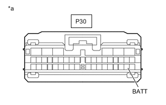
*a Front view of wire harness connector
(to Hydrogen Fuel Control ECU Assembly)
Measure the voltage according to the value(s) in the table below.
Standard Voltage Tester Connection Condition Specified Condition P30-37 (BATT) - Body ground Power switch off 11 to 14 V -
Reconnect the hydrogen fuel control ECU assembly connector.
Result Proceed to OK NG
NG
REPAIR OR REPLACE HARNESS AND CONNECTOR (HYDROGEN FUEL CONTROL ECU ASSEMBLY - AUXILIARY BATTERY)
OK
-
-
CHECK TERMINAL VOLTAGE (IGSW)
-
Disconnect the hydrogen fuel control ECU assembly connector.
-
Turn the power switch on (IG).
-
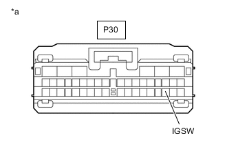
*a Front view of wire harness connector
(to Hydrogen Fuel Control ECU Assembly)
Measure the voltage according to the value(s) in the table below.
Standard Voltage Tester Connection Condition Specified Condition P30-36 (IGSW) - Body ground Power switch on (IG) 11 to 14 V -
Turn the power switch off.
-
Reconnect the hydrogen fuel control ECU assembly connector.
Result Proceed to OK NG
NG
CHECK TERMINAL VOLTAGE (POWER SOURCE OF FC PWR2 RELAY) Click here
OK
-
-
CHECK HARNESS AND CONNECTOR (HYDROGEN FUEL CONTROL ECU ASSEMBLY - BODY GROUND)
-
Disconnect the hydrogen fuel control ECU assembly connector.
-
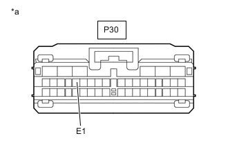
*a Front view of wire harness connector
(to Hydrogen Fuel Control ECU Assembly)
Measure the resistance according to the value(s) in the table below.
Standard Resistance Tester Connection Condition Specified Condition P30-10 (E1) - Body ground Power switch off Below 1 Ω -
Reconnect the hydrogen fuel control ECU assembly connector.
Result Proceed to OK NG
NG
REPAIR OR REPLACE HARNESS OR CONNECTOR (HYDROGEN FUEL CONTROL ECU ASSEMBLY - AUXILIARY BATTERY)
OK
-
-
REPLACE HYDROGEN FUEL CONTROL ECU ASSEMBLY
Result Proceed to NEXT
NEXT
-
CLEAR DTC
-
Connect the GTS to the DLC3.
-
Turn the power switch on (IG).
-
Enter the following menus: Powertrain / EV / Trouble Codes.
-
Clear the DTCs.
Powertrain > EV > Clear DTCs -
Turn the power switch off and wait for 3 minutes or more.
Result Proceed to NEXT
NEXT
-
-
CHECK DTC OUTPUT
-
Connect the GTS to the DLC3.
-
Turn the power switch on (IG) and wait for 2 minutes or more.
-
Enter the following menus: Powertrain / EV / Trouble Codes.
-
Check for DTCs.
Powertrain > EV > Trouble CodesResult Result Proceed to DTCs are not output A DTC U1162-450 is output B -
Turn the power switch off.
A
END
B
REPLACE EV CONTROL ECU Click here
-
-
CHECK TERMINAL VOLTAGE (POWER SOURCE OF FC PWR2 RELAY)
-
Remove the FC PWR2 relay from the motor compartment relay block.
-
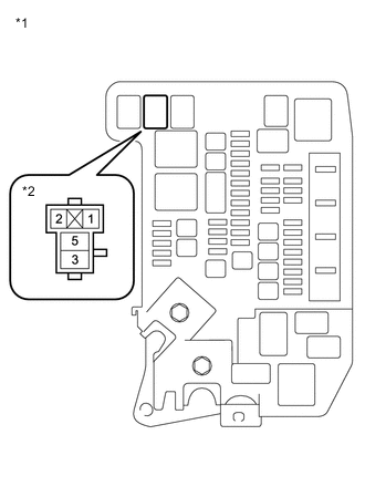
*1 Motor Compartment Relay Block *2 FC PWR2 Relay Holder Measure the voltage according to the value(s) in the table below.
Standard Voltage Tester Connection Condition Specified Condition 5 (FC PWR2 relay holder) - Body ground Power switch off 11 to 14 V -
Reinstall the FC PWR2 relay.
Result Proceed to OK NG
NG
REPAIR OR REPLACE HARNESS AND CONNECTOR (FC PWR2 RELAY - AUXILIARY BATTERY)
OK
-
-
INSPECT RELAY (FC PWR2)
Result Proceed to OK NG
NG
REPLACE RELAY (FC PWR2)
OK
-
CHECK HARNESS AND CONNECTOR (HYDROGEN FUEL CONTROL ECU ASSEMBLY - FC PWR2 RELAY)
-
Disconnect the hydrogen fuel control ECU assembly connector.
-
Remove the FC PWR2 relay from the motor compartment relay block.
-
Measure the resistance according to the value(s) in the table below.
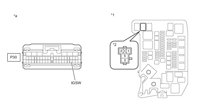
*1 Motor Compartment Relay Block *2 FC PWR2 Relay Holder *a Front view of wire harness connector
(to FC Control ECU)
- - Standard Resistance Tester Connection Condition Specified Condition P30-36 (IGSW) - 3 (FC PWR2 relay holder) Power switch off Below 1 Ω P30-36 (IGSW) or 3 (FC PWR2 relay holder) - Body ground and other terminals Power switch off 10 kΩ or higher -
Reconnect the hydrogen fuel control ECU assembly connector.
-
Reinstall the FC PWR2 relay.
Result Proceed to OK NG
NG
REPAIR OR REPLACE HARNESS AND CONNECTOR
OK
-
-
CHECK TERMINAL VOLTAGE (POWER SOURCE OF FC PWR2 RELAY)
-
Remove the FC PWR2 relay from the motor compartment relay block.
-
Turn the power switch on (IG).
-
*1 Motor Compartment Relay Block *2 FC PWR2 Relay Holder Measure the voltage according to the value(s) in the table below.
Standard Voltage Tester Connection Condition Specified Condition 1 (FC PWR2 relay holder) - Body ground Power switch on (IG) 11 to 14 V -
Turn the power switch off.
-
Reinstall the FC PWR2 relay.
Result Proceed to OK NG
OK
REPAIR OR REPLACE HARNESS AND CONNECTOR (FC PWR2 RELAY - BODY GROUND)
NG
-
-
CHECK HARNESS AND CONNECTOR (HYDROGEN FUEL CONTROL ECU ASSEMBLY - FC PWR2 RELAY)
-
Disconnect the hydrogen fuel control ECU assembly connector.
-
Remove the FC PWR2 relay from the motor compartment relay block.
-
Measure the resistance according to the value(s) in the table below.
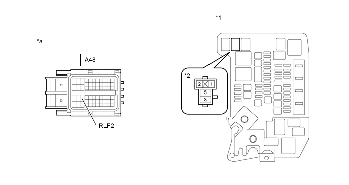
*1 Motor Compartment Relay Block *2 FC PWR2 Relay Holder *a Front view of wire harness connector
(to FC Control ECU)
- - Standard Resistance Tester Connection Condition Specified Condition A48-33 (RLF2) - 1 (FC PWR2 relay holder) Power switch off Below 1 Ω A48-33 (RLF2) or 1 (FC PWR2 relay holder) - Body ground and other terminals Power switch off 10 kΩ or higher -
Reconnect the hydrogen fuel control ECU assembly connector.
-
Reinstall the FC PWR2 relay.
Result Proceed to OK NG
OK
REPLACE FC CONTROL ECU Click here
NG
REPAIR OR REPLACE HARNESS AND CONNECTOR
-
-
CHECK HARNESS AND CONNECTOR (FC LOCAL BUS)
CAUTION:
Be sure to wear insulated gloves.
-
Check that the service plug grip is not installed to FC stack assembly and EV battery.
Note
After removing the service plug grip, do not turn the power switch on (READY), unless instructed by the repair manual because this may cause a malfunction.
-
Disconnect the EV control ECU connector.
-
Disconnect the FC control ECU connector.
-
Disconnect the hydrogen fuel control ECU assembly connector.
-
Disconnect the diagnosis recorder ECU connector.
-
Disconnect the FC converter assembly (FC boost control ECU) connector.
-
Measure the resistance according to the value(s) in the table below.
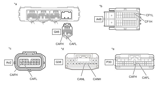
*a Rear view of wire harness connector
(to EV Control ECU)
*b Front view of wire harness connector
(to FC Control ECU)
*c Front view of wire harness connector
(to FC Converter Assembly (FC Boost Control ECU))
*d Front view of wire harness connector
(to Diagnosis Recorder ECU)
*e Front view of wire harness connector
(to Hydrogen Fuel Control ECU Assembly)
- - Standard Resistance Tester Connection Condition Specified Condition G46-31 (CAFH) - Ao2-2 (CAFH) Power switch off Below 1 Ω G46-31 (CAFH) - P30-15 (CAFH) Power switch off Below 1 Ω G46-31 (CAFH) - A48-10 (CF1H) Power switch off Below 1 Ω G46-31 (CAFH) - G38-13 (CANH) Power switch off Below 1 Ω G46-30 (CAFL) - A48-11 (CF1L) Power switch off Below 1 Ω G46-30 (CAFL) - Ao2-8 (CAFL) Power switch off Below 1 Ω G46-30 (CAFL) - P30-16 (CAFL) Power switch off Below 1 Ω G46-30 (CAFL) - G38-12 (CANL) Power switch off Below 1 Ω G46-31 (CAFH), A48-10 (CF1H), Ao2-2 (CAFH), P30-15 (CAFH) or G38-13 (CANH) - Body ground and other terminals Power switch off 10 kΩ or higher G46-30 (CAFL), A48-11 (CF1L), Ao2-8 (CAFL), P30-16 (CAFL) or G38-12 (CANL) - Body ground and other terminals Power switch off 10 kΩ or higher -
Reconnect the EV control ECU connector.
-
Reconnect the FC control ECU connector.
-
Reconnect the hydrogen fuel control ECU assembly connector.
-
Reconnect the FC converter assembly (FC boost control ECU) connector.
-
Reconnect the diagnosis recorder ECU connector.
Result Proceed to OK NG
NG
REPAIR OR REPLACE HARNESS OR CONNECTOR
OK
-
-
INSPECT HYDROGEN FUEL CONTROL ECU ASSEMBLY
-
Disconnect the hydrogen fuel control ECU assembly connector.
-
Measure the resistance according to the value(s) in the table below.

*a Component without harness connected
(Hydrogen Fuel Control ECU Assembly)
- - Standard Resistance Tester Connection Condition Specified Condition P30-15 (CAFH) - P30-16 (CAFL) Always 108 to 132 Ω P30-15 (CAFH) or P30-16 (CAFL) - Body ground and other terminals Always 10 kΩ or higher -
Reconnect the hydrogen fuel control ECU assembly connector.
Result Proceed to OK NG
NG
REPLACE HYDROGEN FUEL CONTROL ECU ASSEMBLY Click here
OK
-
-
INSPECT FC CONTROL ECU
-
Disconnect all the connectors from the FC control ECU.
-
Measure the resistance according to the value(s) in the table below.
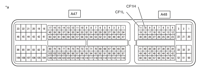
*a Component without harness connected
(FC Control ECU)
- - Standard Resistance Tester Connection Condition Specified Condition A48-10 (CF1H) - A48-11 (CF1L) Always 10 kΩ or higher A48-10 (CF1H) or A48-11 (CF1L) - Body ground and other terminals Always 10 kΩ or higher -
Reconnect all the connectors to the FC control ECU.
Result Proceed to OK NG
NG
REPLACE FC CONTROL ECU Click here
OK
-
-
INSPECT FC CONVERTER ASSEMBLY (FC BOOST CONTROL ECU)
CAUTION:
Be sure to wear insulated gloves.
-
Check that the service plug grip is not installed to FC stack assembly and EV battery.
Note
After removing the service plug grip, do not turn the power switch on (READY), unless instructed by the repair manual because this may cause a malfunction.
-
Disconnect the FC converter assembly (FC boost control ECU) connector.
-
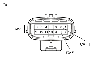
*a Component without harness connected
(FC Converter Assembly (FC Boost Control ECU))
Measure the resistance according to the value(s) in the table below.
Standard Resistance Tester Connection Condition Specified Condition Ao2-2 (CAFH) - Ao2-8 (CAFL) Always 108 to 132 Ω Ao2-2 (CAFH) or Ao2-8 (CAFL) - Body ground and other terminals Always 10 kΩ or higher -
Reconnect the FC converter assembly (FC boost control ECU) connector.
Result Proceed to OK NG
OK
REPLACE DIAGNOSIS RECORDER ECU Click here
NG
REPLACE FC CONVERTER ASSEMBLY Click here
-
-
CHECK HARNESS AND CONNECTOR (FC LOCAL BUS)
CAUTION:
Be sure to wear insulated gloves.
-
Check that the service plug grip is not installed to FC stack assembly and EV battery.
Note
After removing the service plug grip, do not turn the power switch on (READY), unless instructed by the repair manual because this may cause a malfunction.
-
Disconnect the EV control ECU connector.
-
Disconnect the FC control ECU connector.
-
Disconnect the hydrogen fuel control ECU assembly connector.
-
Disconnect the FC converter assembly (FC boost control ECU) connector.
-
Measure the resistance according to the value(s) in the table below.
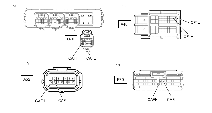
*a Rear view of wire harness connector
(to EV Control ECU)
*b Front view of wire harness connector
(to FC Control ECU)
*c Front view of wire harness connector
(to FC Converter Assembly (FC Boost Control ECU))
*d Front view of wire harness connector
(to Hydrogen Fuel Control ECU Assembly)
Standard Resistance Tester Connection Condition Specified Condition G46-31 (CAFH) - Ao2-2 (CAFH) Power switch off Below 1 Ω G46-31 (CAFH) - P30-15 (CAFH) Power switch off Below 1 Ω G46-31 (CAFH) - A48-10 (CF1H) Power switch off Below 1 Ω G46-30 (CAFL) - A48-11 (CF1L) Power switch off Below 1 Ω G46-30 (CAFL) - Ao2-8 (CAFL) Power switch off Below 1 Ω G46-30 (CAFL) - P30-16 (CAFL) Power switch off Below 1 Ω G46-31 (CAFH), A48-10 (CF1H), Ao2-2 (CAFH) or P30-15 (CAFH) - Body ground and other terminals Power switch off 10 kΩ or higher G46-30 (CAFL), A48-11 (CF1L), Ao2-8 (CAFL) or P30-16 (CAFL) - Body ground and other terminals Power switch off 10 kΩ or higher -
Reconnect the EV control ECU connector.
-
Reconnect the FC control ECU connector.
-
Reconnect the hydrogen fuel control ECU assembly connector.
-
Reconnect the FC converter assembly (FC boost control ECU) connector.
Result Proceed to OK NG
NG
REPAIR OR REPLACE HARNESS OR CONNECTOR
OK
-
-
INSPECT HYDROGEN FUEL CONTROL ECU ASSEMBLY
-
Disconnect the hydrogen fuel control ECU assembly connector.
-
Measure the resistance according to the value(s) in the table below.
*a Component without harness connected
(Hydrogen Fuel Control ECU Assembly)
- - Standard Resistance Tester Connection Condition Specified Condition P30-15 (CAFH) - P30-16 (CAFL) Always 108 to 132 Ω P30-15 (CAFH) or P30-16 (CAFL) - Body ground and other terminals Always 10 kΩ or higher -
Reconnect the hydrogen fuel control ECU assembly connector.
Result Proceed to OK NG
NG
REPLACE HYDROGEN FUEL CONTROL ECU ASSEMBLY Click here
OK
-
-
INSPECT FC CONTROL ECU
-
Disconnect all the connectors from the FC control ECU.
-
Measure the resistance according to the value(s) in the table below.
*a Component without harness connected
(FC Control ECU)
- - Standard Resistance Tester Connection Condition Specified Condition A48-10 (CF1H) - A48-11 (CF1L) Always 10 kΩ or higher A48-10 (CF1H) or A48-11 (CF1L) - Body ground and other terminals Always 10 kΩ or higher -
Reconnect all the connectors to the FC control ECU.
Result Proceed to OK NG
NG
REPLACE FC CONTROL ECU Click here
OK
-
-
INSPECT FC CONVERTER ASSEMBLY (FC BOOST CONTROL ECU)
CAUTION:
Be sure to wear insulated gloves.
-
Check that the service plug grip is not installed to FC stack assembly and EV battery.
Note
After removing the service plug grip, do not turn the power switch on (READY), unless instructed by the repair manual because this may cause a malfunction.
-
Disconnect the FC converter assembly (FC boost control ECU) connector.
-
*a Component without harness connected
(FC Converter Assembly (FC Boost Control ECU))
Measure the resistance according to the value(s) in the table below.
Standard Resistance Tester Connection Condition Specified Condition Ao2-2 (CAFH) - Ao2-8 (CAFL) Always 108 to 132 Ω Ao2-2 (CAFH) or Ao2-8 (CAFL) - Body ground and other terminals Always 10 kΩ or higher -
Reconnect the FC converter assembly (FC boost control ECU) connector.
Result Proceed to OK NG
OK
CHECK FOR INTERMITTENT PROBLEMS
NG
REPLACE FC CONVERTER ASSEMBLY Click here
-