FRAME WIRE REMOVAL
CAUTION / NOTICE / HINT
CAUTION:
-
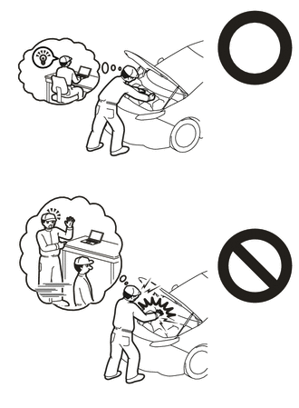
This vehicle has contains high voltage circuits standardized with orange colored wiring and connectors, so follow the instructions in this manual to perform the procedures correctly.
-
If the correct procedures are not followed according to the instructions in this manual, there is a danger of electric shock from the high voltage circuits.
-
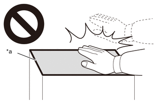
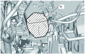
*a High temperature areas If the FC stack assembly and surroundings are hot, do not touch them.
-
Touching the FC stack assembly grip or surroundings when they are hot could result in burns.
-

Be sure to wear insulating gloves when working on high voltage wiring or components.
-
If work is performed without wearing insulating gloves, there is a danger of electric shock.
PROCEDURE
-
PRECAUTION
Note
After turning the power switch off, waiting time may be required before disconnecting the cable from the negative (-) auxiliary battery terminal. Therefore, make sure to read the disconnecting the cable from the negative (-) auxiliary battery terminal notices before proceeding with work.
-
REMOVE SERVICE PLUG GRIP (for EV)
-
REMOVE FC STACK SERVICE PLUG GRIP
-
REMOVE INVERTER COVER
-
REMOVE INVERTER TERMINAL COVER
-
CHECK TERMINAL VOLTAGE
-
INSTALL INVERTER TERMINAL COVER
-
REMOVE CHILD RESTRAINT SEAT ANCHOR BRACKET
-
DISCONNECT FRAME WIRE
CAUTION:
Wear insulated gloves.
-
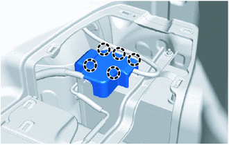
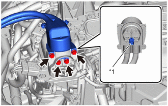
Disengage the 5 claws and remove the battery terminal connector cover from the fusible link block assembly.
-
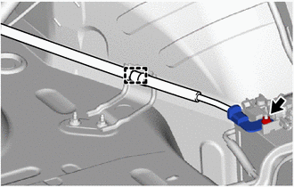
Remove the nut and disconnect the frame wire from the fusible link block assembly.
Note
-
Do not touch the connector terminals.
-
Insulate the terminal portion of the connector by wrapping it with insulating tape.
-
-
Disengage the clamp and disconnect the frame wire from the vehicle.
-
Passenger compartment side:
-
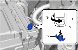
*1 Service Plug Grip *2 Battery Cover Lock Striker *a Projection *b Counterclockwise Using the service plug grip, remove the battery cover lock striker from the EV battery.
Tech Tips
Insert the projection of the service plug grip, turn the button of the battery cover lock striker counterclockwise, and release the lock.
-
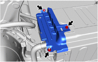
Remove the bolt, 2 nuts and No. 4 EV battery shield panel from the EV battery.
-
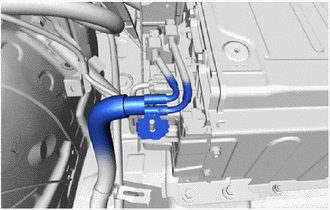
Disengage the shield wire ground of the frame wire from the stud bolt.
-
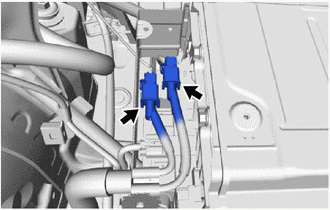
Disconnect the 2 frame wire connectors.
Note
-
Do not touch the connector terminals.
-
Insulate the terminal portion of the connector by wrapping it with insulating tape.
-
-
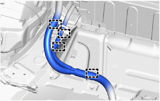
Disengage the 4 clamps and disconnect the frame wire from the vehicle.
-
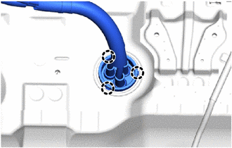
Disengage the 3 claws and disconnect the frame wire grommet, push the frame wire out from the floor panel.
-
-
Motor room side:
-
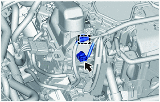
Disconnect the FC inverter input junction cover connector.
-
Disengage the clamp and disconnect the wire harness from the FC inverter input junction cover connector.
-
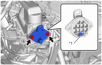
*1 Interlock Connector Using an insulated tool, remove the 2 bolts and FC inverter input junction cover from the FC inverter input junction assembly.
Note
-
The inverter terminal cover has an interlock connector, so pull it up vertically.
-
Do not touch the rubber seal of the inverter terminal cover.
-
-
*1 Interlock Connector Using an insulated tool, remove the 4 bolts and disconnect the frame wire from the FC inverter input junction assembly.
Note
-
The frame wire has an interlock connector, so pull it out straight.
-
When disconnecting, be careful not to damage the terminal portion, connector housing, or FC inverter input junction assembly.
-
Do not touch the rubber seal or terminal portion of the frame wire.
-
Insulate the terminal portion of the frame wire by wrapping it with insulating tape.
-
-
*a Protective Tape To prevent contamination by foreign matter or water droplets, cover the openings of the inverter with converter assembly with protective tape.
-
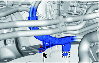
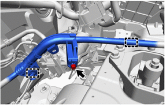
Remove the bolt and disconnect the frame wire from the No. 3 cross member frame bracket sub-assembly RH.
-
Disengage the clamp and disconnect the frame wire from the vehicle.
-
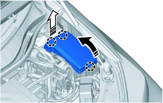

Remove in this Direction (1) 
Remove in this Direction (2) As shown in the illustration disengage the claw and remove the No. 1 relay block cover.
-
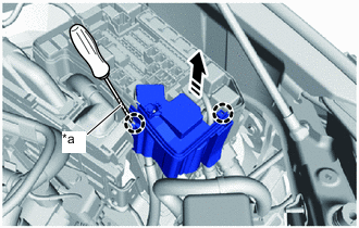
*a Protective Tape Using a screwdriver with its tip wrapped in protective tape, Disengage the 2 claws and disconnect the No. 1 relay block cover from the motor compartment relay block.
-
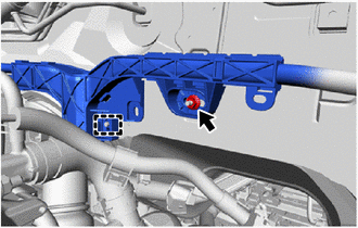
Disengage the clamp and disconnect the No. 2 motor compartment wire from the frame wire.
-
Remove the bolt and disconnect the frame wire from the motor room relay block.
Note
-
Do not touch the connector terminals.
-
Insulate the terminal portion of the connector by wrapping it with insulating tape.
-
-
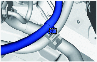
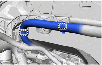
Disengage the clamp and disconnect the frame wire from the vehicle.
-
Disengage the 2 clamps and disconnect the motor room frame wire from the frame wire protector of frame wire.
-
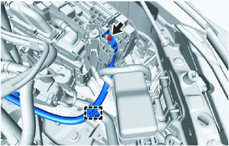
Remove the bolt.
-
Disengage the 2 clamps and disconnect the frame wire from the vehicle.
-
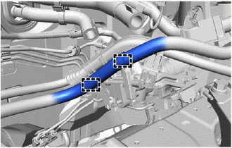
Disengage the 2 clamps and disconnect the motor room frame wire from the frame wire protector of frame wire.
-
Remove the nut.
-
Disengage the clamp and disconnect the frame wire from the vehicle.
-
-
-
REMOVE HYDROGEN TANK UNIT
-
REMOVE FC STACK ASSEMBLY
-
REMOVE FRONT SUSPENSION CROSSMEMBER SUB-ASSEMBLY
-
REMOVE FRAME WIRE
-
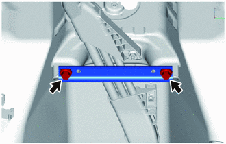
Remove the 2 bolts and front floor center brace from the vehicle.
-
Remove the 4 nuts.
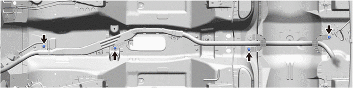
-
Disengage the 8 clamps and remove the frame wire from the vehicle.
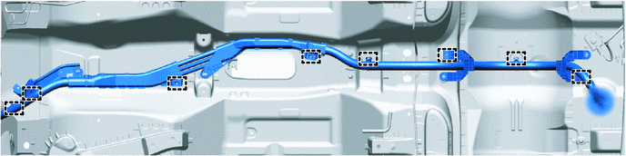
-
Disengage the 2 claws and remove the stud clamp from the frame wire.
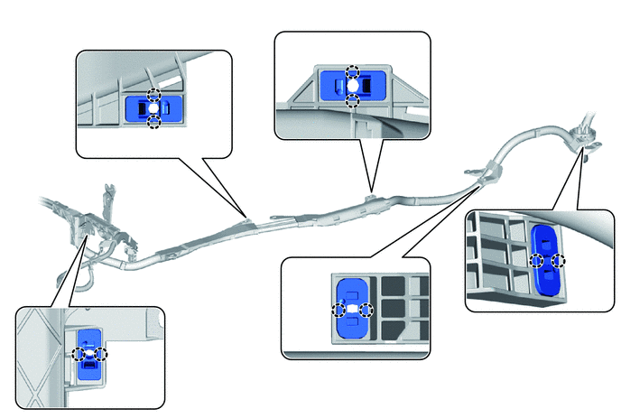
Note
-
When disengaging the stud clamp, make sure not to damage the frame wire protector.
-
The clamps are non-reusable parts.
Tech Tips
-
This procedure is only performed when the frame wire will be reused.
-
Use the same procedure to remove the other 4 stud clamps.
-
-
Remove the 4 clamps (cable tie type) from the frame wire.
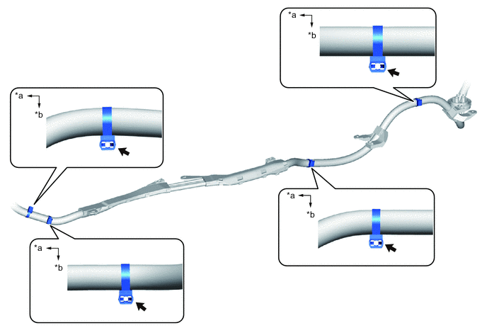
*a Front of the vehicle *b Left side of the vehicle Note
The clamps (cable tie type) cannot be reused.
Tech Tips
This procedure is only performed when the frame wire will be reused.
-