HAZARD WARNING SWITCH REMOVAL
CAUTION / NOTICE / HINT
The necessary procedures (adjustment, calibration, initialization or registration) that must be performed after parts are removed, installed or replaced during the clock assembly removal/installation are shown below.
| Replacement Part or Procedure | Necessary Procedures | Effects / Inoperative when not Performed | Link |
|---|---|---|---|
| Disconnect cable from negative battery terminal | Drive the vehicle until stop and start control is permitted (approximately 5 to 60 minutes) | Stop and start system | |
| Memorize steering angle neutral point | Pre-crash safety system |
Tech Tips
-
Use the same procedure for RHD and LHD vehicles.
-
The procedure listed below is for LHD vehicles.
PROCEDURE
-
PRECAUTION
CAUTION:
Be sure to read Precaution thoroughly before servicing.
for Type A:
for Type B:
for Type C:
Note
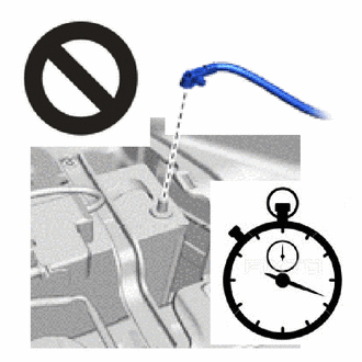
After turning the ignition switch off, waiting time may be required before disconnecting the cable from the negative (-) battery terminal. Therefore, make sure to read the disconnecting the cable from the negative (-) battery terminal notice before proceeding with work.
-
DISCONNECT CABLE FROM NEGATIVE BATTERY TERMINAL
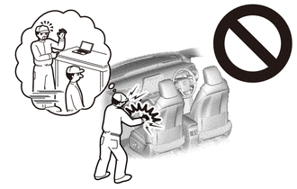
CAUTION:
-
Wait at least 90 seconds after disconnecting the cable from the negative (-) battery terminal to disable the SRS system.
-
If the airbag deploys for any reason, it may cause a serious accident.
Note
When disconnecting the cable, some systems need to be initialized after the cable is reconnected.
-
-
REMOVE UPPER INSTRUMENT PANEL
-
REMOVE DEFROSTER NOZZLE ASSEMBLY (w/ Navigation System)
-
REMOVE NO. 2 HEATER TO REGISTER DUCT SUB-ASSEMBLY (w/ Navigation System)
-
REMOVE NO. 1 HEATER TO REGISTER DUCT SUB-ASSEMBLY (w/ Navigation System)
-
REMOVE NO. 2 HEATER TO REGISTER DUCT (w/ Navigation System)
-
REMOVE CLOCK ASSEMBLY (Hazard Warning Switch)
-
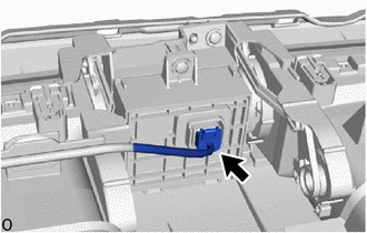
Disconnect the connector.
-
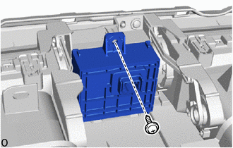
Remove the screw and clock assembly (hazard warning switch).
-