ROOF HEADLINING(for Double Cab) INSTALLATION
CAUTION / NOTICE / HINT
Tech Tips
-
Use the same procedure for RHD and LHD vehicles.
-
The procedure listed below is for LHD vehicles.
-
A bolt without a torque specification is shown in the standard bolt chart.
PROCEDURE
-
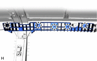
INSTALL REAR NO. 2 SIDE RAIL SPACER LH (w/o Curtain Shield Airbag)
-
Attach the claw to install the rear No. 2 side rail spacer LH.
-
-
INSTALL REAR NO. 2 SIDE RAIL SPACER RH (w/o Curtain Shield Airbag)
-
Attach the claw to install the rear No. 2 side rail spacer RH.
-
-
INSTALL REAR SIDE RAIL SPACER LH (w/o Curtain Shield Airbag)
-
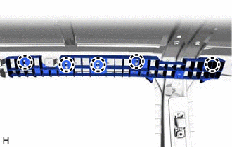
Attach the claw to install the rear side rail spacer LH.
-
-
INSTALL REAR SIDE RAIL SPACER RH (w/o Curtain Shield Airbag)
-
Attach the claw to install the rear side rail spacer RH.
-
-
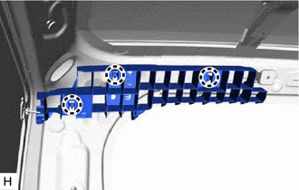
INSTALL FRONT SIDE RAIL SPACER LH (w/o Curtain Shield Airbag)
-
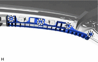
Attach the claw to install the front side rail spacer LH.
-
-
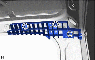
INSTALL FRONT SIDE RAIL SPACER RH (w/o Curtain Shield Airbag)
-
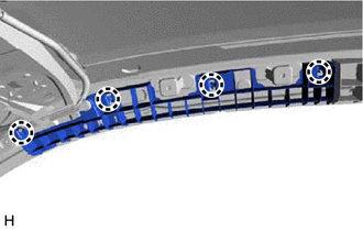
Attach the claw to install the front side rail spacer RH.
-
-
INSTALL ROOF HEADLINING ASSEMBLY
-
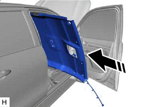

Movement Direction Insert the roof headlining assembly into the cabin from the front door.
Note
-
Check that the corners of the roof headlining assembly are not folded, twisted or otherwise deformed and that none of the mounted parts have fallen off.
-
Make sure that the roof headlining assembly does not get caught on anything as it may become bent or damaged.
-
Do not damage the roof headlining assembly or vehicle interior.
-
-
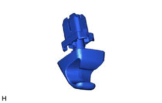
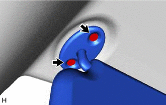
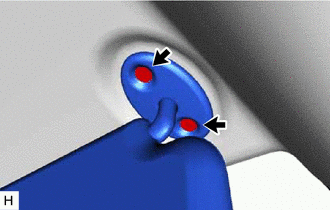
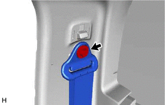
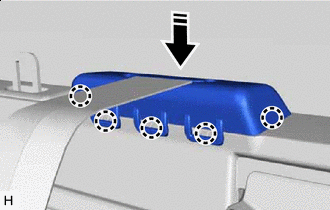
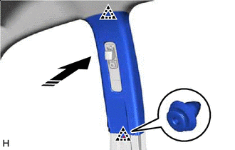
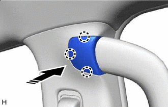
Install the visor holder as shown in the illustration.
-
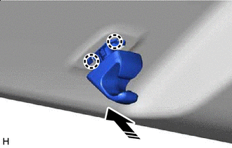
Install in this Direction Attach the claw to install the visor holder as shown in the illustration.
Tech Tips
Use the same procedure for both visor holders.
-
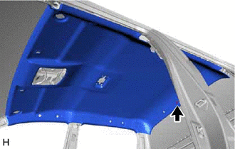
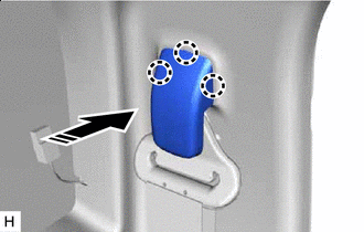
Install the roof headlining assembly with the clip.
-
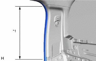
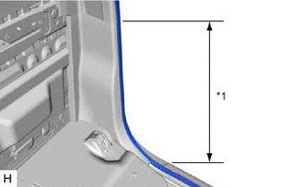
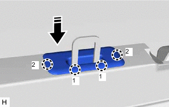
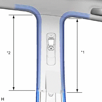
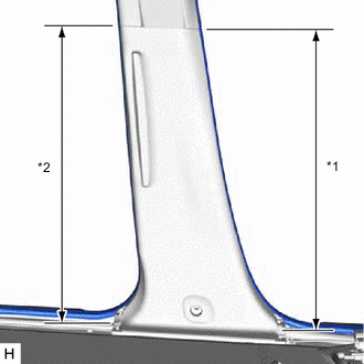
Connect the front door opening trim weatherstrip LH and rear door opening trim weatherstrip LH in the range shown in the illustration.
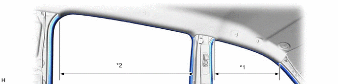
*1 Front Door Opening Trim Weatherstrip LH *2 Rear Door Opening Trim Weatherstrip LH -
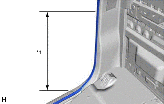
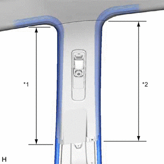
Connect the front door opening trim weatherstrip RH and rear door opening trim weatherstrip RH in the range shown in the illustration.
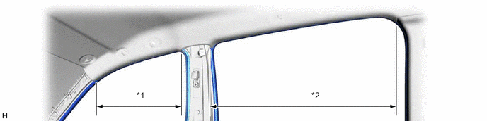
*1 Front Door Opening Trim Weatherstrip RH *2 Rear Door Opening Trim Weatherstrip RH -
w/ Pre-crash Safety System:
-
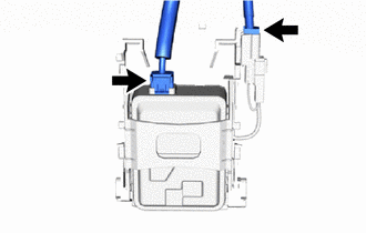
w/ Camera Heater:
Connect the 2 connectors.
-
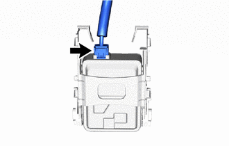
w/o Camera Heater:
Connect the connector.
-
-
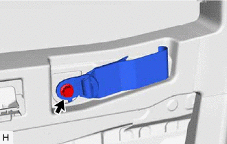
w/o Pre-crash Safety System:
-
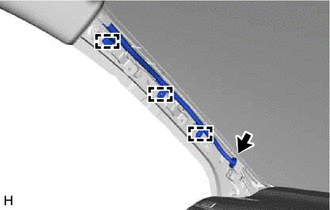
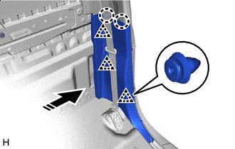
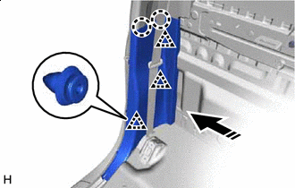
Connect the connector and attach the clamp to the front pillar LH.
-
-
w/ Pre-crash Safety System:
-
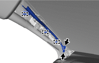
Connect the connector and attach the clamp to he front pillar LH.
-
-
-
INSTALL ROOF HEADLINING SERVICE HOLE COVER (w/o Assist Grip)
-
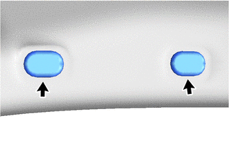
Install the 2 roof headlining service hole covers.
-
-
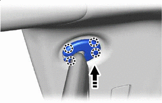
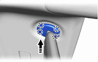
INSTALL COAT HOOK SUB-ASSEMBLY
Tech Tips
Use the same procedure for both coat hook sub-assemblies.
-
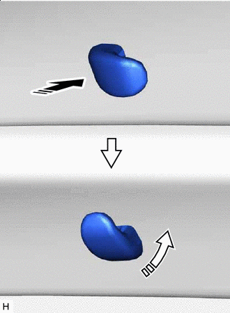
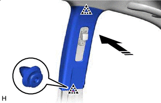
Install in this Direction (1) 
Install in this Direction (2) Insert the coat hook sub-assembly and rotate it 90° counterclockwise to install it as shown in the illustration.
-
-
INSTALL ASSIST GRIP SUB-ASSEMBLY
Tech Tips
Use the same procedure for all assist grip sub-assemblies.
-
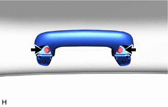
Install the assist grip sub-assembly with the 2 bolts.
-
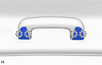
Attach the claw to close the assist grip cover.
-
-
INSTALL VISOR ASSEMBLY LH
-
Install the visor assembly LH with the 2 screws.
-
Connect the visor assembly LH to the visor holder.
-
-
INSTALL VISOR ASSEMBLY RH
-
Install the visor assembly RH with the 2 screws.
-
Connect the visor assembly RH to the visor holder.
-
-
INSTALL VISOR BRACKET COVER LH
-
Install in this Direction Attach the claw to install the visor bracket cover LH as shown in the illustration.
-
-
INSTALL VISOR BRACKET COVER RH
-
Install in this Direction Attach the claw to install the visor bracket cover RH as shown in the illustration.
-
-
INSTALL NO. 1 FORWARD RECOGNITION COVER (w/ Pre-crash Safety System)
-
INSTALL NO. 1 ROOM LIGHT ASSEMBLY
-
INSTALL MAP LIGHT ASSEMBLY
-
INSTALL INNER REAR VIEW MIRROR ASSEMBLY
-
INSTALL QUARTER INSIDE TRIM BOARD LH
-
Install in this Direction Attach the clip to install the quarter inside trim board LH as shown in the illustration.
-
*1 Rear Door Opening Trim Weatherstrip LH Connect the rear door opening trim weatherstrip LH in the range shown in the illustration.
-
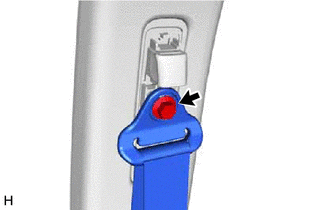
Connect the rear seat outer belt assembly LH with the bolt.
- Torque:
- 42 N*m { 428 kgf*cm, 31 ft.*lbf }
-
-
INSTALL QUARTER INSIDE TRIM BOARD RH
-
Install in this Direction Attach the clip to install the quarter inside trim board RH as shown in the illustration.
-
*1 Rear Door Opening Trim Weatherstrip RH Connect the rear door opening trim weatherstrip RH in the range shown in the illustration.
-
Connect the rear seat outer belt assembly RH with the bolt.
- Torque:
- 42 N*m { 428 kgf*cm, 31 ft.*lbf }
-
-
INSTALL SEAT BELT ANCHOR COVER CAP
Tech Tips
Use the same procedure for seat belt anchor cover caps.
-
Install in this Direction Attach the claw to install the seat belt anchor cover cap as shown in the illustration.
-
-
INSTALL LOWER QUARTER TRIM PANEL LH
-
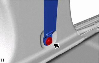
Installation Direction Attach the clip and claw to install the lower quarter trim panel LH as shown in the illustration.
-
*1 Rear Door Opening Trim Weatherstrip LH Connect the rear door opening trim weatherstrip LH in the range shown in the illustration.
-
-
INSTALL LOWER QUARTER TRIM PANEL RH
-
Install in this Direction Attach the clip and claw to install the lower quarter trim panel RH as shown in the illustration.
-
*1 Rear Door Opening Trim Weatherstrip RH Connect the rear door opening trim weatherstrip RH in the range shown in the illustration.
-
-
INSTALL UPPER BACK PANEL GARNISH
-
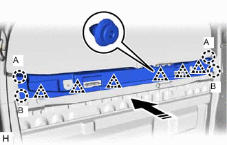
Install in this Direction Attach the clip and claw to install the upper back panel garnish as shown in the illustration.
Tech Tips
Lower claw A into position and then push claw B toward the rear of the vehicle to attach the claws.
-
Install in this Direction Attach the claw to connect the belt guide as shown in the illustration.
-
Install in this Direction Attach the claw to install the back panel trim cover as shown in the illustration.
Tech Tips
Attach the claws in the order shown in the illustration.
-
-
INSTALL TETHER ANCHOR BRACKET SUB-ASSEMBLY
Tech Tips
Use the same procedure for both tether anchor bracket sub-assemblies.
-
Install the tether anchor bracket sub-assembly with the bolt.
- Torque:
- 42 N*m { 428 kgf*cm, 31 ft.*lbf }
-
-
INSTALL REAR SEATBACK HOLDER
-
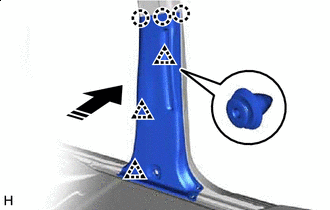
INSTALL UPPER CENTER PILLAR GARNISH LH
-
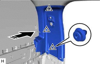
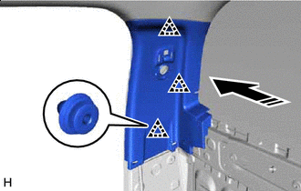
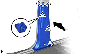
Install in this Direction Attach the clip to install the upper center pillar garnish LH as shown in the illustration.
-
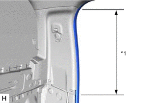
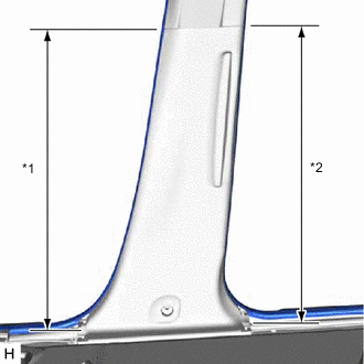
*1 Front Door Opening Trim Weatherstrip LH *2 Rear Door Opening Trim Weatherstrip LH Connect the front door opening trim weatherstrip LH and rear door opening trim weatherstrip LH in the range shown in the illustration.
-
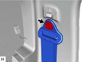
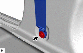
Connect the front seat outer belt assembly LH with the bolt.
- Torque:
- 42 N*m { 428 kgf*cm, 31 ft.*lbf }
-
-
INSTALL UPPER CENTER PILLAR GARNISH RH
-
Install in this Direction Attach the clip to install the upper center pillar garnish RH as shown in the illustration.
-
*1 Front Door Opening Trim Weatherstrip RH *2 Rear Door Opening Trim Weatherstrip RH Connect the front door opening trim weatherstrip RH and rear door opening trim weatherstrip RH in the range shown in the illustration.
-
Connect the front seat outer belt assembly RH with the bolt.
- Torque:
- 42 N*m { 428 kgf*cm, 31 ft.*lbf }
-
-
INSTALL SEAT BELT ANCHOR COVER CAP
Tech Tips
Use the same procedure for both seat belt anchor cover caps.
-
Install in this Direction Attach the claw to install the seat belt anchor cover cap as shown in the illustration.
-
-
INSTALL PILLAR ASSIST GRIP ASSEMBLY
Tech Tips
Use the same procedure for both pillar assist grip assemblies.
-
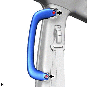
Install the pillar assist grip assembly with the 2 bolts.
-
-
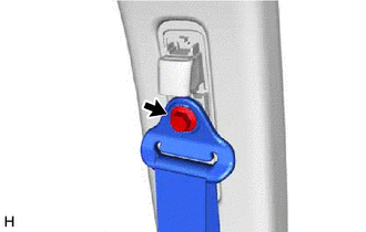
INSTALL ASSIST GRIP PLUG LH
Tech Tips
Use the same procedure for both assist grip plugs.
-
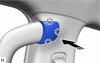
Install in this Direction Attach the claw to install the assist grip plug LH as shown in the illustration.
-
-
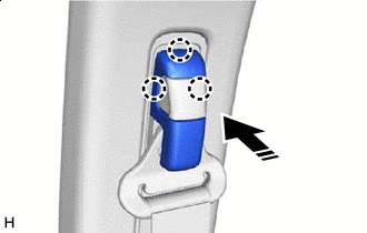
INSTALL ASSIST GRIP PLUG RH
Tech Tips
Use the same procedure for both assist grip plugs.
-
Install in this Direction Attach the claw to install the assist grip plug RH as shown in the illustration.
-
-
INSTALL LOWER CENTER PILLAR GARNISH LH
-
Install in this Direction Attach the clip and claw to install the lower center pillar garnish LH as shown in the illustration.
-
*1 Front Door Opening Trim Weatherstrip LH *2 Rear Door Opening Trim Weatherstrip LH Connect the front door opening trim weatherstrip LH and rear door opening trim weatherstrip LH in the range shown in the illustration.
-
Connect the front seat outer belt assembly LH with the bolt.
- Torque:
- 42 N*m { 428 kgf*cm, 31 ft.*lbf }
-
-
INSTALL LOWER CENTER PILLAR GARNISH RH
-
Install in this Direction Attach the clip and claw to install the lower center pillar garnish RH as shown in the illustration.
-
*1 Front Door Opening Trim Weatherstrip RH *2 Rear Door Opening Trim Weatherstrip RH Connect the front door opening trim weatherstrip RH and rear door opening trim weatherstrip RH in the range shown in the illustration.
-
Connect the front seat outer belt assembly RH with the bolt.
- Torque:
- 42 N*m { 428 kgf*cm, 31 ft.*lbf }
-
-
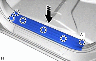
INSTALL REAR DOOR SCUFF PLATE LH
-
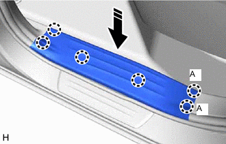
Install in this Direction Attach the claw to install the rear door scuff plate LH as shown in the illustration.
Tech Tips
Attach claw A shown in the illustration first.
-
-
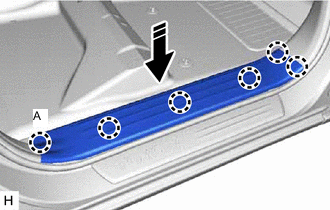
INSTALL REAR DOOR SCUFF PLATE RH
-
Install in this Direction Attach the claw to install the rear door scuff plate RH as shown in the illustration.
Tech Tips
Attach claw A shown in the illustration first.
-
-
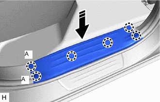
INSTALL FRONT DOOR SCUFF PLATE LH
-
Install in this Direction Attach the claw to install the front door scuff plate LH as shown in the illustration.
Tech Tips
Attach claw A shown in the illustration first.
-
-
INSTALL FRONT DOOR SCUFF PLATE RH
-
Install in this Direction Attach the claw to install the front door scuff plate RH as shown in the illustration.
Tech Tips
Attach claw A shown in the illustration first.
-
-
INSTALL FRONT PILLAR GARNISH LH
-
INSTALL FRONT PILLAR GARNISH RH
-
INSTALL ASSIST GRIP SUB-ASSEMBLY (w/ Assist Grip)
-
INSTALL FRONT CONSOLE BOX (w/o Console Box Lid)
-
INSTALL REAR CONSOLE BOX SUB-ASSEMBLY (w/ Rear Console Box)
-
INSTALL CONSOLE BOX ASSEMBLY (w/ Console Box Lid)
-
INSTALL REAR SEAT ASSEMBLY
-
for Seat Cushion 60/40 Split Type:
-
for Seat Cushion Bench Type:
-
-
INSTALL FRONT SEAT ASSEMBLY LH
-
for Manual Seat:
-
for Power Seat:
-
for Bench Seat Type:
-
-
INSTALL FRONT SEAT ASSEMBLY RH
-
CONNECT CABLE TO NEGATIVE BATTERY TERMINAL (w/ Airbag System)
Note
When disconnecting the cable, some systems need to be initialized after the cable is reconnected.
-
CHECK SRS WARNING LIGHT (w/ Airbag System)