METER / GAUGE SYSTEM Speedometer Malfunction
DESCRIPTION
-
The combination meter assembly receives vehicle speed signals from the brake actuator assembly (skid control ECU) via the CAN communication line. The wheel speed sensors output voltages that vary according to the vehicle speed. The brake actuator assembly (skid control ECU) supplies power to the wheel speed sensors. The brake actuator assembly (skid control ECU) calculates the vehicle speed based on the pulses of the voltage.
w/ ABS:
-
The combination meter assembly receives vehicle speed signals from the speedometer sensor. The wheel speed sensors output voltages that vary according to the vehicle speed. The speedometer sensor calculates the vehicle speed based on the pulses of the voltage.
w/o ABS:
WIRING DIAGRAM
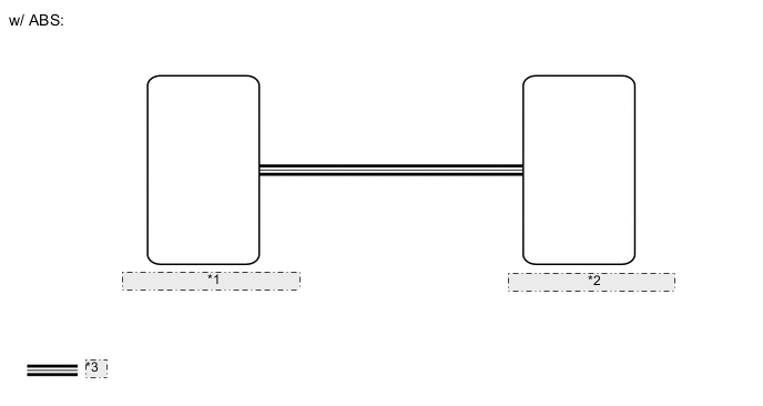
| *1 | Brake Actuator Assembly (Skid Control ECU) |
| *2 | Combination Meter Assembly |
| *3 | CAN Communication Line |
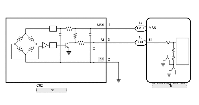
| *a | SE |
| *b | Combination Meter Assembly |
| *c | Speedometer Sensor |
CAUTION / NOTICE / HINT
Note
-
When replacing the combination meter assembly, make sure to replace it with a new one.
-
If the vehicle speed is outside the allowable range when tested, perform the operation check.
Tech Tips
Before starting the following inspection, check tire size and tire air pressure.
PROCEDURE
-
CHECK VEHICLE TYPE
-
Check vehicle type.
Result Result Proceed to w/ ABS A w/o ABS B
B 
CHECK COMBINATION METER ASSEMBLY Click here
A 
-
-
CHECK FOR DTC (CAN COMMUNICATION SYSTEM)
-
Check for DTCs.
for LHD: Click here
for RHD: Click here
OK No DTCs are output. Result Result Proceed to OK (w/ VSC) A OK (w/o VSC) B NG C
B
CHECK FOR DTC (ANTI-LOCK BRAKE SYSTEM) Click here
C 
GO TO CAN COMMUNICATION SYSTEM for LHD: Click here
GO TO CAN COMMUNICATION SYSTEM for RHD: Click hereA
-
-
CHECK FOR DTC (VEHICLE STABILITY CONTROL SYSTEM)
-
Check for DTCs.
Chassis > ABS/VSC/TRC > Trouble CodesOK No DTCs are output. Result Proceed to OK NG
NG
GO TO VEHICLE STABILITY CONTROL SYSTEM Click here
OK
-
-
PERFORM ACTIVE TEST USING GTS (SPEED METER OPERATION)
-
Using the GTS, perform the Active Test.
Body Electrical > Combination Meter > Active TestTester Display Measurement Item Control Range Diagnostic Note Speed Meter Operation Speedometer
-
OFF, 0, 40, 80, 120, 160 or 200 (km/h) (for km/h)
-
OFF, 0, 40, 80 or 100 (mph) (for mph)
There is a deviation in the values displayed on the speedometer display (Control range → Speedometer)
-
40 → 41.7 to 46.2
-
80 → 83.4 to 88.4
-
120 → 125.1 to 130.6
-
160 → 166.2 to 173.2
-
180 → 186.9 to 194.5
for km/h (Type A)
-
40 → 41.4 to 45.9
-
80 → 82.7 to 87.7
-
120 → 124.1 to 129.1
-
160 → 165.4 to 170.4
for km/h (Type B)
-
40 → 41.0 to 45.5
-
80 → 82 to 87
-
120 → 123.1 to 128.1
-
160 → 164.1 to 169.1
for km/h (Type C)
-
40 → 40.5 to 45
-
80 → 81 to 86
-
120 → 121.4 to 126.4
-
160 → 161.9 to 166.9
for km/h (Type D)
-
40 → 40.6 to 45.1
-
80 → 81.3 to 86.3
-
120 → 121.9 to 126.9
-
160 → 162.5 to 167.5
for km/h (Type E)
-
40 → 42 to 44.5
-
80 → 83.1 to 87.1
for mph
Body Electrical > Combination Meter > Active TestTester Display Speed Meter Operation OK Speedometer indication is normal. Result Proceed to OK NG -
NG
REPLACE COMBINATION METER ASSEMBLY Click here
OK
-
-
READ VALUE USING GTS (VEHICLE SPEED METER)
-
Using the GTS, read the Data List.
Body Electrical > Combination Meter > Data ListTester Display Measurement Item Range Normal Condition Diagnostic Note Vehicle Speed Meter Vehicle speed Min.: 0 km/h (0 mph), Max.: 255 km/h (158 mph) Almost the same as actual vehicle speed -
Body Electrical > Combination Meter > Data ListTester Display Vehicle Speed Meter Tech Tips
-
When the Data List values of the ECUs match, an internal malfunction of the combination meter assembly is suspected.
-
When the Data List values of the ECUs do not match, a signal output error of the brake actuator assembly (skid control ECU) or an internal malfunction of the combination meter assembly is suspected.
OK Vehicle speed displayed on the GTS is almost the same as the actual vehicle speed measured using a speedometer tester (calibrated chassis dynamometer). Result Proceed to OK NG -
OK
REPLACE COMBINATION METER ASSEMBLY Click here
NG
-
-
READ VALUE USING GTS (VEHICLE SPEED)
-
Using the GTS, read the Data List.
Chassis > ABS/VSC/TRC > Data ListTester Display Measurement Item Normal Condition Reference Value Diagnostic Note Vehicle Speed Vehicle speed Min.: 0 km/h (0 mph), Max.: 326 km/h (202 mph) Almost the same as actual vehicle speed -
Chassis > ABS/VSC/TRC > Data ListTester Display Vehicle Speed OK Vehicle speed displayed on the GTS is almost the same as the actual vehicle speed measured using a speedometer tester (calibrated chassis dynamometer). Result Proceed to OK NG
NG
REPLACE BRAKE ACTUATOR ASSEMBLY (SKID CONTROL ECU) w/ VSC: Click here
REPLACE BRAKE ACTUATOR ASSEMBLY (SKID CONTROL ECU) w/o VSC: Click hereOK
-
-
CHECK COMBINATION METER ASSEMBLY
-
Replace the combination meter assembly with a new one.
-
Check that the operation of the speedometer returns to normal.
OK The operation of the speedometer returns to normal. Result Proceed to OK NG
OK
END (COMBINATION METER ASSEMBLY IS DEFECTIVE)
NG
REPLACE BRAKE ACTUATOR ASSEMBLY (SKID CONTROL ECU) w/ VSC: Click here
REPLACE BRAKE ACTUATOR ASSEMBLY (SKID CONTROL ECU) w/o VSC: Click here -
-
CHECK FOR DTC (ANTI-LOCK BRAKE SYSTEM)
-
Check for DTCs.
Chassis > ABS/VSC/TRC > Trouble CodesOK No DTCs are output. Result Proceed to OK NG
OK
GO TO STEP 4 Click here
NG
GO TO ANTI-LOCK BRAKE SYSTEM Click here
-
-
CHECK COMBINATION METER ASSEMBLY
-
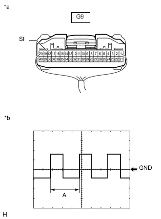
*a Component with harness connected
(Combination Meter Assembly)
*b Waveform Remove the combination meter assembly with the connector(s) still connected.
-
Connect an oscilloscope to terminal G9-18 (SI) and body ground.
-
Check the signal waveform according to the condition(s) in the table below.
Measurement Condition Item Condition Tester Connection G9-18 (SI) - Body ground Tool Setting 5 V/DIV, 20 ms./DIV Vehicle Condition Driving at approximately 20 km/h (12 mph) Tech Tips
When the system is functioning normally, one wheel revolution generates 4 pulses. As the vehicle speed increases, the width indicated by A in the illustration narrows.
OK The waveform displayed is as shown in the illustration. Result Proceed to OK NG
OK
REPLACE COMBINATION METER ASSEMBLY Click here
NG
-
-
CHECK HARNESS AND CONNECTOR (SPEEDOMETER SENSOR - COMBINATION METER ASSEMBLY AND BODY GROUND)
-
Disconnect the C62 speedometer sensor connector.
-
Disconnect the G9 and G10 combination meter assembly connectors.
-
Measure the resistance according to the value (s) in the table below.
Standard Resistance Tester Connection Condition Specified Condition C62-1 (MS5) - G10-14 (MS5) Always Below 1 Ω C62-3 (SI) - G9-18 (SI) Always Below 1 Ω C62-2 (SE) - Body ground Always Below 1 Ω C62-1 (MS5) or G10-14 (MS5) - Body ground Always 10 kΩ or higher C62-3 (SI) or G9-9 (SI) - Body ground Always 10 kΩ or higher Result Proceed to OK NG
NG
REPAIR OR REPLACE HARNESS OR CONNECTOR
OK
-
-
CHECK COMBINATION METER ASSEMBLY (OUTPUT VOLTAGE)
-
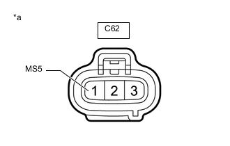
*a Front view of wire harness connector
(to Speedometer Sensor)
Disconnect the speedometer sensor connector.
-
Measure the voltage according to the value(s) in the table below.
Standard Voltage Tester Connection Switch Condition Specified Condition C62-1 (MS5) - Body ground Ignition switch ON 11 to 14 V Ignition switch off Below 1 V Result Proceed to OK NG
OK
REPLACE SPEEDOMETER SENSOR Click here
NG
REPLACE COMBINATION METER ASSEMBLY Click here
-