REAR DOOR LOCK(for Smart Cab) REMOVAL
CAUTION / NOTICE / HINT
The necessary procedures (adjustment, calibration, initialization or registration) that must be performed after parts are removed, installed or replaced during the upper access panel lock assembly or lower access panel lock assembly removal/installation are shown below.
| Replacement Part or Procedure | Necessary Procedures | Effects / Inoperative when not Performed | Link |
|---|---|---|---|
| Disconnect cable from negative battery terminal | Drive the vehicle until stop and start control is permitted (approximately 5 to 60 minutes) | Stop and start system | |
| Memorize steering angle neutral point | Pre-crash safety system |
Tech Tips
-
Use the same procedure for the RH and LH sides.
-
The procedure listed below is for the LH side.
PROCEDURE
-
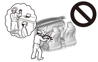
PRECAUTION (w/ Airbag System)
CAUTION:
Be sure to read Precaution thoroughly before servicing.
for Type A:
for Type B:
for Type C:
Note
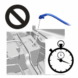
After turning the ignition switch off, waiting time may be required before disconnecting the cable from the negative (-) battery terminal. Therefore, make sure to read the disconnecting the cable from the negative (-) battery terminal notice before proceeding with work.
-
DISCONNECT CABLE FROM NEGATIVE BATTERY TERMINAL (w/ Airbag System)
CAUTION:
-
Wait at least 90 seconds after disconnecting the cable from the negative (-) battery terminal to disable the SRS system.
-
If the airbag deploys for any reason, it may cause a serious accident.
Note
When disconnecting the cable, some systems need to be initialized after the cable is reconnected.
-
-
REMOVE LAP BELT OUTER ANCHOR COVER
-
REMOVE REAR DOOR TRIM BOARD SUB-ASSEMBLY LH
-
REMOVE SEAT BELT ANCHOR COVER CAP
-
REMOVE FRONT SEAT OUTER BELT ASSEMBLY LH
-
REMOVE REAR DOOR FRAME GARNISH LH
-
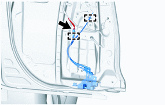
REMOVE UPPER ACCESS PANEL LOCK ASSEMBLY LH
-
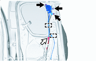

Bolt 
Connector Disconnect the connector and detach the clamp.
-
Remove the 3 bolts and upper access panel lock assembly LH.
-
Disconnect the cable from the access panel lock remote control assembly LH and detach the clamp.
-
-
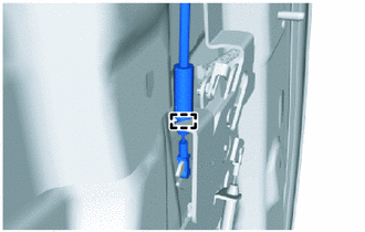
REMOVE LOWER ACCESS PANEL LOCK ASSEMBLY LH
-
Disconnect the cable from the access panel lock remote control and detach the clamp.
-
Disconnect the connector and detach the clamp.
-
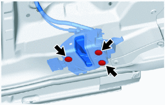
Using a T30 "TORX" socket wrench, remove the 3 bolts.
-
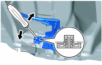
*1 Grommet Using a screwdriver, pry up the grommet from the stud bolt.
-
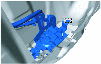
Detach the hook and remove the lower access panel lock assembly LH.
-