MAIN BODY ECU(for LHD) REMOVAL
CAUTION / NOTICE / HINT
The necessary procedures (adjustment, calibration, initialization or registration) that must be performed after parts are removed, installed or replaced during the body ECU removal/installation are shown below.
| Replacement Part or Procedure | Necessary Procedures | Effect/Inoperative Function when Necessary Procedures not Performed | Link |
|---|---|---|---|
| Disconnect cable from negative battery terminal | Drive the vehicle until stop and start control is permitted (approximately 5 to 60 minutes) | Stop and start system | |
| Memorize steering angle neutral point | Pre-collision system | ||
| Body ECU | Initialize automatic light control system | Automatic light control system |
PROCEDURE
-
PRECAUTION
CAUTION:
Be sure to read Precaution thoroughly before servicing.
for Type A:
for Type B:
for Type C:
Note
After turning the ignition switch off, waiting time may be required before disconnecting the cable from the negative (-) battery terminal. Therefore, make sure to read the disconnecting the cable from the negative (-) battery terminal notice before proceeding with work.
-
DISCONNECT CABLE FROM NEGATIVE BATTERY TERMINAL
CAUTION:
-
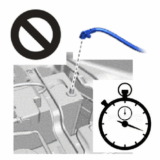
Wait at least 90 seconds after disconnecting the cable from the negative (-) battery terminal to disable the SRS system.
-
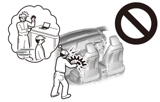
If the airbag deploys for any reason, it may cause a serious accident.
Note
When disconnecting the cable, some systems need to be initialized after the cable is reconnected.
-
-
REMOVE NO. 1 INSTRUMENT PANEL UNDER COVER SUB-ASSEMBLY
-
REMOVE LOWER STEERING COLUMN COVER
-
REMOVE LOWER NO. 1 INSTRUMENT PANEL AIRBAG ASSEMBLY
-
REMOVE INSTRUMENT PANEL JUNCTION BLOCK ASSEMBLY
-
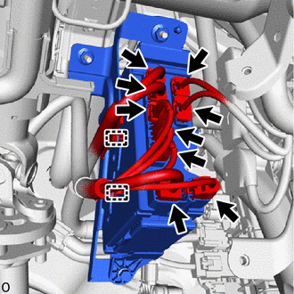
Disconnect the front side of the 9 connectors.
-
Detach the 2 wire harness clamps.
-
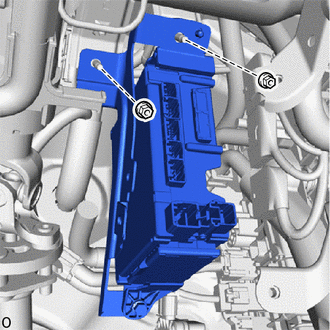
Remove the 2 nuts and instrument panel junction block assembly.
-
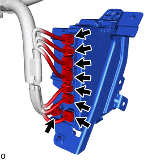
Disconnect the back side of the 8 connectors.
-
-
REMOVE WIRE HARNESS CLAMP BRACKET
-
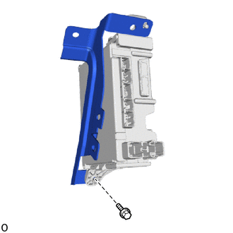
Remove the bolt and wire harness clamp bracket.
-
-
REMOVE BODY ECU
-
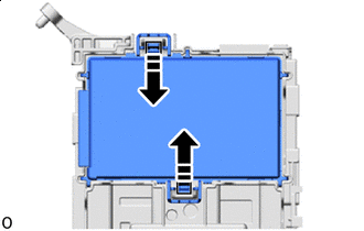

Press in this Direction Press the 2 levers of the body ECU to release the lock.
-
Insert in this Direction 
Raise in this Direction 
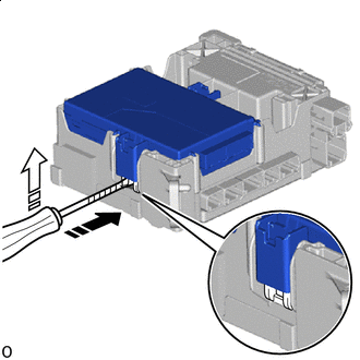
Protective Tape With the body ECU released, insert a screwdriver with its tip wrapped with protective tape horizontally between the body ECU and junction block.
Note
-
Use a screwdriver with a diameter between 5.0 mm (0.197 in.) and 6.3 mm (0.248 in.) and a length of approximately 90 mm (3.54 in.).
-
Do not insert the screwdriver under the connector socket of the body ECU.
-
-
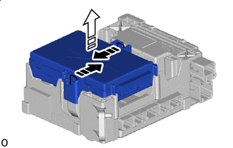
Press in this Direction Remove in this Direction Press the 2 levers of the body ECU again and pull up the body ECU to remove it.
Note
Do not touch the ECU connector.
-