DESCRIPTION
The skid control ECU (brake actuator assembly) is connected to the combination meter assembly via CAN communication.
The slip indicator light blinks during VSC and/or TRC operation.
If a malfunction is detected, the slip indicator light comes on to warn the driver.
w/ Rear Differential Lock:
When the rear differential cannot be unlocked for 2 consecutive trips, the slip indicator light illuminates.
CAUTION / NOTICE / HINT
-
When replacing the skid control ECU (brake actuator assembly), perform zero point calibration and store system information.
-
w/o Stop and Start System:
Inspect the fuses for circuits related to this system before performing the following inspection procedure.
-
w/ Rear Differential Lock:
As there may be malfunctions in the differential system related to when the system operates with the rear differential locked, check the differential system first.
PROCEDURE
- Click here
CHECK CAN COMMUNICATION SYSTEM
-
Check if CAN communication system DTCs are output.
for LHD with Central Gateway ECU:Click here
for RHD with Central Gateway ECU:Click here
for LHD without Central Gateway ECU:Click here
for RHD without Central Gateway ECU:Click here
Result Proceed to DTC is not output DTC is output
- DTC is not outputClick here
- DTC is output
CHECK CAN COMMUNICATION SYSTEM for LHD with Central Gateway ECU:Click here
CHECK CAN COMMUNICATION SYSTEM for RHD with Central Gateway ECU:Click here
CHECK CAN COMMUNICATION SYSTEM for LHD without Central Gateway ECU:Click here
CHECK CAN COMMUNICATION SYSTEM for RHD without Central Gateway ECU:Click here
-
- Click here
CHECK IF SKID CONTROL ECU CONNECTOR IS SECURELY CONNECTED
-
Check if the skid control ECU (brake actuator assembly) connector is securely connected.
OK The connector is securely connected. Result Proceed to OK NG
- OKClick here
- NG
CONNECT CONNECTOR TO ECU CORRECTLY
-
- Click here
INSPECT BATTERY
-
Check the battery voltage.
Standard voltage 11 to 14 V Result Proceed to OK NG
- OKClick here
- NG
CHECK OR REPLACE CHARGING SYSTEM OR BATTERY for 1GD-FTV:Click here
CHECK OR REPLACE CHARGING SYSTEM OR BATTERY for 2GD-FTV:Click here
CHECK OR REPLACE CHARGING SYSTEM OR BATTERY for 2KD-FTV:Click here
CHECK OR REPLACE CHARGING SYSTEM OR BATTERY for 1TR-FE:Click here
CHECK OR REPLACE CHARGING SYSTEM OR BATTERY for 2TR-FE:Click here
CHECK OR REPLACE CHARGING SYSTEM OR BATTERY for 1GR-FE:Click here
-
- Click here
CHECK TERMINAL VOLTAGE (IG1 TERMINAL)
-
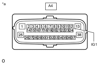
*a Front view of wire harness connector
(to Skid Control ECU [Brake Actuator Assembly])
Disconnect the A4 skid control ECU (brake actuator assembly) connector.
-
Turn the ignition switch to ON.
-
Measure the voltage according to the value(s) in the table below.
Standard Voltage Tester Connection Switch Condition Specified Condition A4-12 (IG1) - Body ground Ignition switch ON 10.5 to 16 V*1 11 to 14 V*2
-
*1: w/ Stop and Start System
-
*2: w/o Stop and Start System
Result Proceed to OK NG (w/ Stop and Start System) NG (w/o Stop and Start System) -
- OKClick here
- NG (w/ Stop and Start System)
INSPECT STOP AND START SYSTEM (BACKUP BOOST CONVERTER CIRCUIT)Click here
- NG (w/o Stop and Start System)
REPAIR OR REPLACE HARNESS OR CONNECTOR (IG1 CIRCUIT)
-
- Click here
CHECK HARNESS AND CONNECTOR (GND1 TERMINAL)
-
Turn the ignition switch off.
-
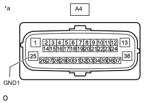
*a Front view of wire harness connector
(to Skid Control ECU [Brake Actuator Assembly])
Measure the resistance according to the value(s) in the table below.
Standard Resistance Tester Connection Condition Specified Condition A4-25 (GND1) - Body ground Always Below 1 Ω Result Proceed to OK NG
- OKClick here
- NG
REPAIR OR REPLACE HARNESS OR CONNECTOR (GND1 CIRCUIT)
-
- Click here
READ VALUE USING GTS (SLIP INDICATOR LIGHT)
-
Reconnect the A4 skid control ECU (brake actuator assembly) connector.
-
Connect the GTS to the DLC3.
-
Turn the ignition switch to ON.
-
Turn the GTS on.
-
Enter the following menus: Chassis / ABS/VSC/TRC / Data List.
-
According to the display on the GTS, read the Data List.
- Chassis > ABS/VSC/TRC > Data List
Tester Display Measurement Item Range Normal Condition Diagnostic Note Slip Indicator Light SLIP indicator light OFF or ON OFF: Indicator light off
ON: Indicator light on
- -
-
- Chassis > ABS/VSC/TRC > Data List
Tester Display Slip Indicator Light -
-
-
-
- Chassis > ABS/VSC/TRC > Data List
-
Check the GTS display condition of the slip indicator light.
Result Proceed to Display of the Data List remains OFF Display of the Data List remains ON
- Display of the Data List remains OFF
INSPECT METER / GAUGE SYSTEMClick here
- Display of the Data List remains ON
REPLACE BRAKE ACTUATOR ASSEMBLYClick here
-