VEHICLE STABILITY CONTROL SYSTEM, Diagnostic DTC:C1268

| DTC Code | DTC Name |
|---|---|
| C1268 | Transfer L4 Position Switch Circuit |
DESCRIPTION
| DTC No. | Detection Item | DTC Detection Condition | Trouble Area |
|---|---|---|---|
| C1268 | Transfer L4 Position Switch Circuit | Either of the following is detected:
|
|
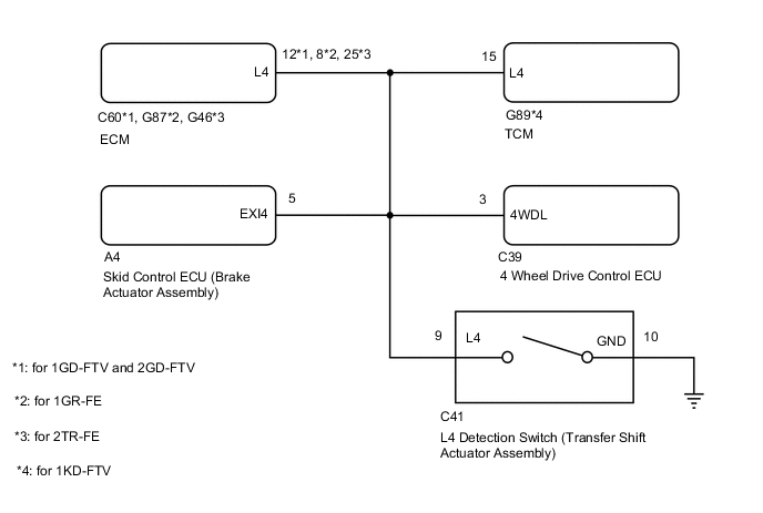
WIRING DIAGRAM
CAUTION / NOTICE / HINT
Note
When replacing the skid control ECU (brake actuator assembly), perform zero point calibration and store system information.
Tech Tips
When DTC U0114 is output together with DTC C1268, inspect and repair the trouble areas indicated by DTC U0114 first.
PROCEDURE
-
INSPECT TOUCH SELECT 2-4 AND HIGH-LOW SYSTEM
-
Turn the 4WD control switch (transfer position switch) to L4, and then drive the vehicle and check that there are no problems with the touch select 2-4 and high-low system.
OK There are no problems with the touch select 2-4 and high-low system. Result Result OK NG
NG 
GO TO TOUCH SELECT 2-4 AND HIGH-LOW SYSTEM Click here
OK 
-
-
CHECK HARNESS AND CONNECTOR (EXI4 TERMINAL)
-
Connect the A4 skid control ECU (brake actuator assembly) connector.
-
Turn the 4WD control switch (transfer position switch) to L4.
-
Disconnect the C60*1, G87*2 or G46*3 ECM connector.
-
*1: for 1GD-FTV and 2GD-FTV
-
*2: for 1GR-FE
-
*3: for 2TR-FE
-
-
Disconnect the G89* TCM connector.
-
*: for 1KD-FTV
-
-
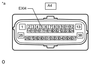
*a Front view of wire harness connector
(to Skid Control ECU [Brake Actuator Assembly])
Disconnect the A4 skid control ECU (brake actuator assembly) connector.
-
Measure the voltage according to the value(s) in the table below.
Standard Voltage Tester Connection Switch Condition Specified Condition A4-5 (EXI4) - Body ground
-
Ignition switch ON
-
4WD control switch (transfer position switch) set to L4
Below 1.5 V -
-
Reconnect the A4 skid control ECU (brake actuator assembly) connector.
-
Reconnect the C60*1, G87*2 or G46*3 ECM connector.
-
*1: for 1GD-FTV and 2GD-FTV
-
*2: for 1GR-FE
-
*3: for 2TR-FE
-
-
Reconnect the G89* TCM connector.
-
*: for 1KD-FTV
-
-
Turn the 4WD control switch (transfer position switch) to H2 or H4.
-
Disconnect the C60*1, G87*2 or G46*3 ECM connector.
-
*1: for 1GD-FTV and 2GD-FTV
-
*2: for 1GR-FE
-
*3: for 2TR-FE
-
-
Disconnect the G89* TCM connector.
-
*: for 1KD-FTV
-
-
Disconnect the A4 skid control ECU (brake actuator assembly) connector.
-
Measure the voltage according to the value(s) in the table below.
Standard Voltage Tester Connection Switch Condition Specified Condition A4-5 (EXI4) - Body ground
-
Ignition switch ON
-
4WD control switch (transfer position switch) set to H2 or H4
11 to 14 V Result Proceed to OK NG -
NG
REPAIR OR REPLACE HARNESS OR CONNECTOR (EXI4 CIRCUIT)
OK
-
-
RECONFIRM DTC
-
Turn the ignition switch off.
-
Reconnect the A4 skid control ECU (brake actuator assembly) connector.
-
Reconnect the C60*1, G87*2 or G46*3 ECM connector.
-
*1: for 1GD-FTV and 2GD-FTV
-
*2: for 1GR-FE
-
*3: for 2TR-FE
-
-
Reconnect the G89* TCM connector.
-
*: for 1KD-FTV
-
-
Turn the ignition switch to ON.
-
Clear the DTC.
Chassis > ABS/VSC/TRC > Clear DTCs -
Turn the ignition switch off.
-
Start the engine.
-
Turn the 4WD control switch (transfer position switch) to H2 or H4.
-
Turn the 4WD control switch (transfer position switch) to L4, drive the vehicle, and then check for DTCs.
Chassis > ABS/VSC/TRC > Trouble CodesResult Proceed to DTC is output DTC is not output
DTC is output
REPLACE BRAKE ACTUATOR ASSEMBLY Click here
DTC is not output
USE SIMULATION METHOD TO CHECK Click here
-