FRONT STABILIZER BAR(for 2WD) REMOVAL
CAUTION / NOTICE / HINT
The necessary procedures (adjustment, calibration, initialization, or registration) that must be performed after parts are removed, installed, or replaced during the front stabilizer bar removal/installation are shown below.
| Necessary Procedure After Parts Removed/Installed/Replaced | ||||||||
|---|---|---|---|---|---|---|---|---|
|
PROCEDURE
-
REMOVE FRONT WHEEL
-
REMOVE NO. 1 ENGINE UNDER COVER ASSEMBLY (w/ Engine Under Cover Assembly)
-
REMOVE ENGINE UNDER BRACE SUB-ASSEMBLY
-
REMOVE FRONT STABILIZER LINK ASSEMBLY LH
-
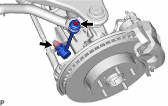
Remove the 2 nuts, 2 retainers, 2 cushions and front stabilizer link assembly LH.
Tech Tips
If the ball joint turns together with the nut, use a 6 mm hexagon wrench to hold the stud in place.
-
-
REMOVE FRONT STABILIZER LINK ASSEMBLY RH
Tech Tips
Use the same procedure described for the LH side.
-
REMOVE FRONT STABILIZER BRACKET
-
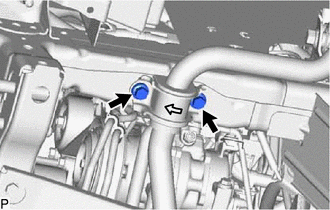
Remove the 4 bolts and 2 front stabilizer brackets.
-
-
REMOVE FRONT NO. 1 STABILIZER BAR BUSH
-
Remove the 2 front No. 1 stabilizer bar bushes.
-
-
REMOVE FRONT STABILIZER BAR
-
Remove the front stabilizer bar from the vehicle body.
-