FRONT LOWER SUSPENSION ARM(for 2WD) REMOVAL

CAUTION / NOTICE / HINT
The necessary procedures (adjustment, calibration, initialization, or registration) that must be performed after parts are removed, installed, or replaced during the front lower suspension arm removal/installation are shown below.
| Necessary Procedure After Parts Removed/Installed/Replaced | ||||||||
|---|---|---|---|---|---|---|---|---|
|
Tech Tips
-
Use the same procedure for the RH and LH sides.
-
The procedure listed below is for the LH side.
PROCEDURE
-
REMOVE FRONT WHEEL
-
REMOVE NO. 1 ENGINE UNDER COVER ASSEMBLY (w/ Engine Under Cover Assembly)
-
DISCONNECT FRONT SPEED SENSOR LH (w/ ABS)
-
Remove the bolt and disconnect the front speed sensor LH.
-
-
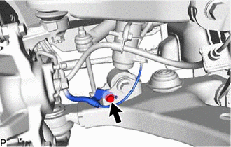
DISCONNECT FRONT SHOCK ABSORBER WITH COIL SPRING
-
Remove the nut and bolt.
Tech Tips
While fixing the nut in place, loosen and remove the bolt.
-
Disconnect the front shock absorber with coil spring from the front lower No. 1 suspension arm sub-assembly LH.
-
-
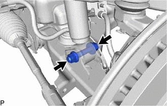
DISCONNECT FRONT STABILIZER LINK ASSEMBLY LH
-
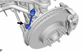
Remove the nut and disconnect the front stabilizer link assembly LH from the front lower No. 1 suspension arm sub-assembly LH.
Tech Tips
If the ball joint turns together with the nut, use a 6 mm hexagon wrench to hold the stud in place.
-
-
REMOVE FRONT NO. 1 SPRING BUMPER SUB-ASSEMBLY
-
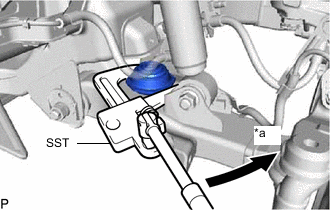
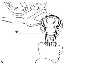
*a Turn Using SST, remove the front No. 1 spring bumper sub-assembly.
- SST
- 09922-10010
Note
Rotate SST in the direction shown in the illustration.
-
-
REMOVE FRONT LOWER NO. 1 SUSPENSION ARM SUB-ASSEMBLY LH
-
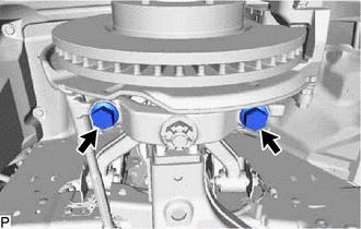
Remove the 2 bolts, and disconnect the front lower ball joint attachment LH from the steering knuckle.
-
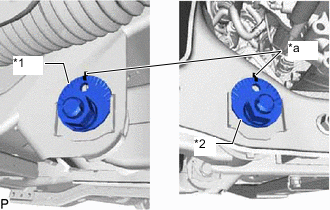
*1 No. 1 Camber Adjusting Cam *2 No. 2 Camber Adjusting Cam *a Matchmark Place matchmarks on the No. 1 camber adjusting cam and vehicle frame, and No. 2 camber adjusting cam and vehicle frame.
-
Remove the 2 nuts, No. 1 and No. 2 camber adjusting cams, 2 camber adjusting cams and front lower No. 1 suspension arm sub-assembly LH.
-
-
REMOVE FRONT LOWER BALL JOINT ATTACHMENT LH
-
Remove the cotter pin and nut.
-
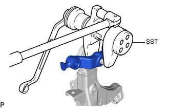
Using SST, remove the front lower ball joint attachment LH.
- SST
- 09628-00011
-
-
REMOVE FRONT LOWER NO. 2 ARM BUSH LH
-
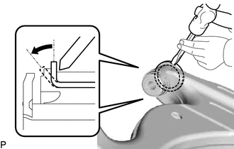
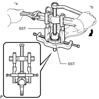
Using a hammer and chisel, strike and bend the entire flange of the bush as shown in the illustration.
-
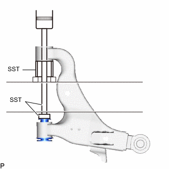
Using SST and a press, press out the front lower No. 2 arm bush LH.
- SST
- 09632-36010
- 09950-00020
-
-
REMOVE FRONT LOWER NO. 1 ARM BUSH LH
-
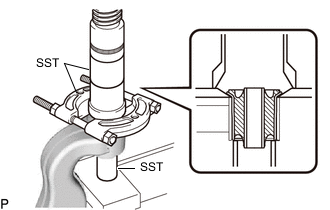
Using SST and a press, press out the front lower No. 1 arm bush LH.
- SST
- 09710-14013 ( 09710-00021 )
- 09950-60010 ( 09951-00410 )
- 09950-70010 ( 09951-07360 )
-
-
REMOVE FRONT LOWER BALL JOINT ASSEMBLY LH
-
*a Protective tape Using 2 screwdrivers and a hammer, remove the snap ring.
Tech Tips
Tape the screwdriver tip before use.
-
*a Hold *b Turn Using SST, remove the front lower ball joint assembly LH.
- SST
- 09950-40011 ( 09951-04010, 09952-04010, 09953-04020, 09954-04010, 09955-04031, 09957-04010, 09958-04011 )
- 09710-22021 ( 09710-01081 )
-