FRONT DRIVE SHAFT ASSEMBLY REMOVAL

CAUTION / NOTICE / HINT
The necessary procedures (adjustment, calibration, initialization, or registration) that must be performed after parts are removed, installed, or replaced during the front drive shaft assembly removal/installation are shown below.
| Necessary Procedure After Parts Removed/Installed/Replaced | ||||||||||||
|---|---|---|---|---|---|---|---|---|---|---|---|---|
|
CAUTION / NOTICE / HINT
Tech Tips
-
Use the same procedure for the RH and LH sides.
-
The procedure listed below is for the LH side.
PROCEDURE
-
REMOVE FRONT WHEEL
-
REMOVE NO. 1 ENGINE UNDER COVER
-
REMOVE NO. 2 ENGINE UNDER COVER
-
DRAIN DIFFERENTIAL OIL
-
REMOVE FRONT AXLE HUB GREASE CAP LH
-
REMOVE FRONT AXLE SHAFT NUT LH
-
DISCONNECT FRONT SPEED SENSOR LH
-
DISCONNECT TIE ROD END SUB-ASSEMBLY LH
-
DISCONNECT FRONT LOWER SUSPENSION ARM ASSEMBLY LH
-
REMOVE FRONT DRIVE SHAFT ASSEMBLY LH
-
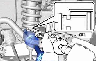
Using SST, remove the front drive shaft assembly LH.
- SST
- 09520-01010
- 09520-24010 ( 09520-32040 )
Note
-
Do not damage the differential side gear shaft oil seal LH, inboard joint boot and front drive shaft dust cover LH.
-
Do not drop the front drive shaft assembly LH.
-
When carrying the front drive shaft assembly LH, hold it horizontally.
Tech Tips
Hook the SST claw at the position shown in the illustration to remove the front drive shaft assembly LH.
-
-
REMOVE FRONT DRIVE SHAFT HOLE SNAP RING
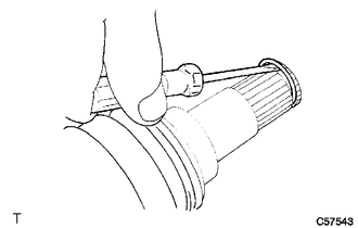
-
Using a screwdriver, remove the front drive shaft hole snap ring.
Note
Do not damage the spline of the inboard joint.
-