RADIO RECEIVER REMOVAL
CAUTION / NOTICE / HINT
Tech Tips
-
Use the same procedure for RHD and LHD vehicles.
-
The procedure listed below is for LHD vehicles.
The necessary procedures (adjustment, calibration, initialization or registration) that must be performed after parts are removed, installed or replaced during the radio receiver removal/installation are shown below.
| Replacement Part or Procedure | Necessary Procedures | Effects / Inoperative when not Performed | Link |
|---|---|---|---|
| Disconnect cable from negative battery terminal | Drive the vehicle until stop and start control is permitted (approximately 5 to 60 minutes) | Stop and start system | |
| Memorize steering angle neutral point | Pre-crash safety system |
CAUTION:
w/ Airbag System:
Some of these service operations affect the SRS airbag system. Read the precautionary notices concerning the SRS airbag system before servicing.
PROCEDURE
-
PRECAUTION
Note
After turning the ignition switch off, waiting time may be required before disconnecting the cable from the battery terminal. Therefore, make sure to read the disconnecting the cable from the battery terminal notice before proceeding with work Click here.
-
DISCONNECT CABLE FROM NEGATIVE BATTERY TERMINAL
CAUTION:
Wait at least 90 seconds after disconnecting the cable from the negative (-) battery terminal to disable the SRS system.
Note
When disconnecting the cable, some systems need to be initialized after the cable is reconnected Click here.
-
REMOVE STEERING WHEEL ASSEMBLY
-
REMOVE INSTRUMENT CLUSTER FINISH PANEL GARNISH ASSEMBLY
-
REMOVE NO. 1 INSTRUMENT PANEL BOX DOOR SUB-ASSEMBLY
-
REMOVE INSTRUMENT CLUSTER FINISH PANEL ASSEMBLY
-
REMOVE CONTROL KNOB SUB-ASSEMBLY (for Manual Cooler System)
-
REMOVE AIR INLET DAMPER CONTROL LEVER (for Manual Cooler System)
-
REMOVE INTEGRATION PANEL SUB-ASSEMBLY WITH AIR CONDITIONING CONTROL ASSEMBLY (for Manual Cooler System)
-
DISCONNECT DEFROSTER DAMPER CONTROL CABLE SUB-ASSEMBLY (for Manual Cooler System)
-
DISCONNECT AIR INLET DAMPER CONTROL CABLE SUB-ASSEMBLY (for Manual Cooler System)
-
REMOVE CONTROL KNOB SUB-ASSEMBLY (for Manual Air Conditioning System)
-
REMOVE AIR INLET DAMPER CONTROL LEVER (for Manual Air Conditioning System)
-
REMOVE INTEGRATION PANEL SUB-ASSEMBLY WITH AIR CONDITIONING CONTROL ASSEMBLY (for Manual Air Conditioning System)
-
DISCONNECT DEFROSTER DAMPER CONTROL CABLE SUB-ASSEMBLY (for Manual Air Conditioning System)
-
DISCONNECT AIR INLET DAMPER CONTROL CABLE SUB-ASSEMBLY (for Manual Air Conditioning System)
-
DISCONNECT AIR MIX DAMPER CONTROL CABLE SUB-ASSEMBLY (for Manual Air Conditioning System)
-
REMOVE AIR CONDITIONING CONTROL ASSEMBLY (for Automatic Air Conditioning System)
-
REMOVE RADIO RECEIVER ASSEMBLY WITH BRACKET (for Radio Receiver Type)
-
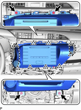

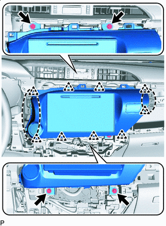
Place Hands Here Remove the 4 screws.
-
Pull out the radio receiver assembly to detach the clips on the backside of the radio receiver assembly with bracket.
-
Disconnect all the connectors and remove the radio receiver assembly with bracket.
-
-
REMOVE NO. 1 RADIO BRACKET (for Radio Receiver Type)
-
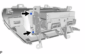
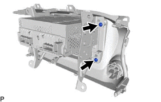
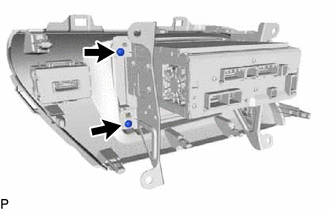
Remove the 2 screws.
-
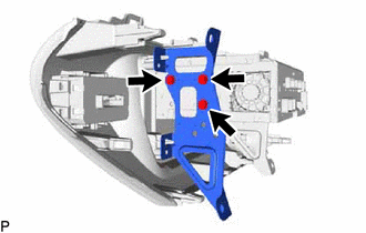
Remove the 3 screws and No. 1 radio bracket from the radio receiver assembly.
-
-
REMOVE NO. 2 RADIO BRACKET (for Radio Receiver Type)
-
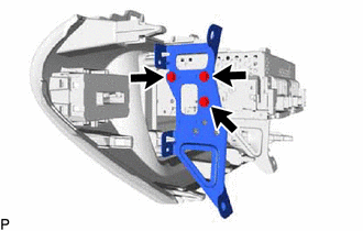
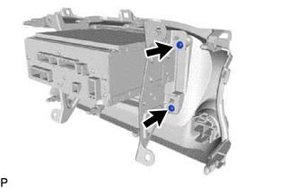
Remove the 2 screws.
-
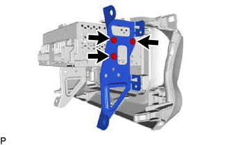
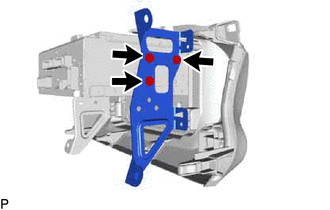
Remove the 3 screws and No. 2 radio bracket from the radio receiver assembly.
-
-
REMOVE RADIO RECEIVER ASSEMBLY (for Radio Receiver Type)
-
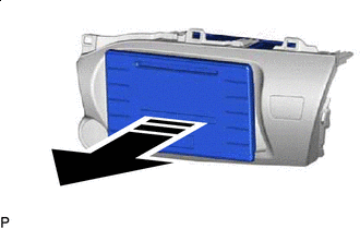

Remove in this Direction Remove the radio receiver assembly in the direction of the arrow shown in the illustration.
-
-
REMOVE RADIO AND DISPLAY RECEIVER ASSEMBLY WITH BRACKET (for Radio and Display Type)
-
Place Hands Here Remove the 4 screws.
-
Pull out the radio and display receiver assembly to detach the clips on the backside of the radio and display receiver assembly with bracket.
-
Disconnect all the connectors and remove the radio and display receiver assembly with bracket.
-
-
REMOVE NO. 1 RADIO BRACKET (for Radio and Display Type)
-
Remove the 2 screws.
-
Remove the 3 screws and No. 1 radio bracket from the radio and display receiver assembly.
-
-
REMOVE NO. 2 RADIO BRACKET (for Radio and Display Type)
-
Remove the 2 screws.
-
Remove the 3 screws and No. 2 radio bracket from the radio and display receiver assembly.
-
-
REMOVE RADIO AND DISPLAY RECEIVER ASSEMBLY (for Radio and Display Type)
-
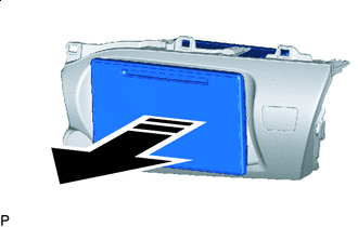
Remove in this Direction Remove the radio and display receiver assembly in the direction of the arrow shown in the illustration.
-