| DTC Code | DTC Name |
|---|---|
| B157D | DAB Tuner Antenna Disconnected |
DESCRIPTION
This DTC is stored when a malfunction occurs in the digital audio broadcasting antenna assembly which is connected to the radio and display receiver assembly.
| DTC No. | Detection Item | DTC Detection Condition | Trouble Area |
|---|---|---|---|
| B157D | DAB Tuner Antenna Disconnected | The windshild glass (window glass antenna wire) is not connected |
|
CAUTION / NOTICE / HINT
When replacing the radio and display receiver assembly, it is necessary to perform the vehicle contract setting for Connected Services (w/ Connected Services Function).
PROCEDURE
- Click here
CHECK DTC
-
Clear the DTCs.
- Body Electrical > Navigation System > Clear DTCs
-
-
-
Recheck for DTCs and check that no DTCs are output.
- Body Electrical > Navigation System > Trouble Codes
-
-
OK No DTCs are output. Result Proceed to OK NG
- OK
USE SIMULATION METHOD TO CHECK
- NGClick here
-
- Click here
CHECK CONNECTION OF DAB RADIO ANTENNA CABLE
-
Check if the DAB radio antenna cable is securely connected to the radio and display receiver assembly.
OK DAB radio antenna cable is securely connected. Result Proceed to OK NG
- OKClick here
- NG
SECURELY CONNECT DAB RADIO ANTENNA CABLE
-
- Click here
CHECK WINDSHIELD GLASS (WINDOW GLASS ANTENNA WIRE)
-
Inspect the windshield glass (window glass antenna wire).
Result Proceed to OK NG
- OKClick here
- NG
REPAIR WINDSHIELD GLASS (WINDOW GLASS ANTENNA WIRE)Click here
-
- Click here
CHECK ANTENNA CORD SUB-ASSEMBLY
-
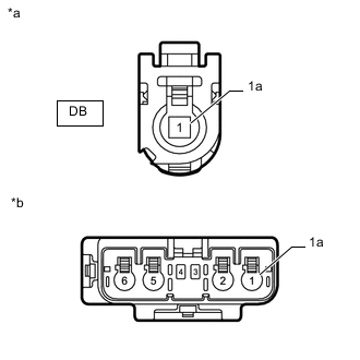
*a Front view of wire harness connector
(to Radio and Display Receiver Assembly)
*b Front view of wire harness connector
(to No. 2 Antenna Cord Sub-assembly)
Remove the antenna connector from the radio and display receiver assembly.
-
Remove the antenna connector from the No. 2 antenna cord sub-assembly.
-
Measure the resistance according to the value(s) in the table below.
Standard Resistance Tester Connection Condition Specified Condition DB-1 - 1 Always Below 1 Ω DB-1a - 1a Always Below 1 Ω DB-1 - Body ground Always 10 kΩ or higher DB-1a - Body ground Always 10 kΩ or higher Result Proceed to OK NG
- OKClick here
- NG
REPLACE ANTENNA CORD SUB-ASSEMBLYClick here
-
- Click here
CHECK NO. 2 ANTENNA CORD SUB-ASSEMBLY
-
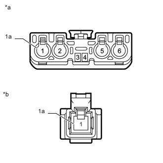
*a Front view of wire harness connector
(to Antenna Cord Sub-assembly)
*b Front view of wire harness connector
(to Digital Audio Broadcasting Antenna Assembly)
Remove the antenna connector from the antenna cord sub-assembly.
-
Remove the antenna connector from the digital audio broadcasting antenna assembly.
-
Measure the resistance according to the value(s) in the table below.
Standard Resistance Tester Connection Condition Specified Condition 1 - 1 Always Below 1 Ω 1a - 1a Always Below 1 Ω 1 - Body ground Always 10 kΩ or higher 1a - Body ground Always 10 kΩ or higher Result Proceed to OK NG
- OK
REPLACE RADIO AND DISPLAY RECEIVER ASSEMBLYClick here
- NG
REPLACE NO. 2 ANTENNA CORD SUB-ASSEMBLYClick here
-