EXHAUST MANIFOLD W/ TURBOCHARGER INSTALLATION
PROCEDURE
-
INSTALL NO. 1 TURBO WATER PIPE SUB-ASSEMBLY
-
*1 New Gasket Install a new gasket and No. 1 turbo water pipe sub-assembly with the 2 bolt and nuts.
- Torque:
- for bolt
- 8.0 N*m { 82 kgf*cm, 71 in.*lbf }
- for nut
- 12 N*m { 122 kgf*cm, 9 ft.*lbf }
-
-
INSTALL EXHAUST MANIFOLD WITH TURBOCHARGER SUB-ASSEMBLY
-
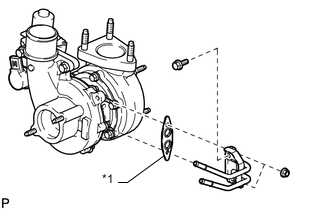
Install a new gasket and the turbocharger sub-assembly with 3 new nuts to the exhaust manifold.
- Torque:
- 52 N*m { 530 kgf*cm, 38 ft.*lbf }
-
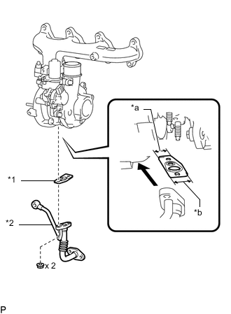
*1 New Gasket *2 Turbo Oil Inlet Pipe Sub-assembly *a Narrow *b Wide 
Outside Install a new gasket and the turbo oil inlet pipe sub-assembly with the 2 nuts, but only loosely install the nuts.
Note
The notch (wide part) of the gasket must face the engine.
-
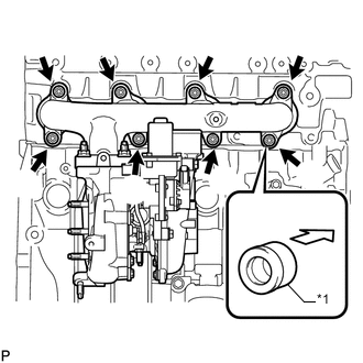
*1 Collar 
Engine Side Temporarily install the exhaust manifold with turbocharger sub-assembly, 8 collars and the 8 plate washers to the cylinder head sub-assembly with 8 new nuts.
Note
Make sure that the side of the collar with the smaller diameter faces the exhaust manifold.
-
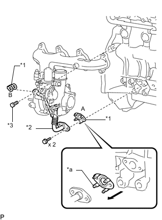
*1 New Gasket *2 Turbo Oil Inlet Pipe Sub-assembly *3 Union Bolt *a Claw Turbo Oil Inlet Pipe Side Install a new gasket (labeled A) and the turbo oil inlet pipe sub-assembly with the 2 bolts, but only loosely install the bolts.
Note
The claws of the gasket must face the turbo oil inlet pipe sub-assembly.
-
Install a new gasket (labeled B) and the turbo oil inlet pipe sub-assembly with the union bolt, but only loosely install the union bolt.
-
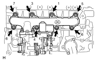
Tighten the exhaust manifold with turbocharger sub-assembly, to the cylinder head sub-assembly with 8 nuts.
- Torque:
- 40 N*m { 408 kgf*cm, 30 ft.*lbf }
Tech Tips
Tighten the nuts in the order shown in the illustration.
-
Tighten the 2 nuts and union bolt of the turbo oil inlet pipe sub-assembly, and the 2 bolts.
- Torque:
- for nut
- 13 N*m { 133 kgf*cm, 10 ft.*lbf }
- for union bolt
- 26 N*m { 265 kgf*cm, 19 ft.*lbf }
- for bolt
- 12 N*m { 122 kgf*cm, 9 ft.*lbf }
Tech Tips
Tighten the nut, union bolt and bolt in that order.
-
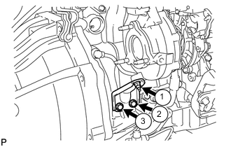
Install the 2 bolts and the nut of the turbocharger stay in the order shown in the illustration.
- Torque:
- 38 N*m { 387 kgf*cm, 28 ft.*lbf }
-
-
INSTALL TURBINE OUTLET ELBOW
-
Install a new gasket and the turbine outlet elbow to the turbocharger sub-assembly with new 3 nuts.
- Torque:
- 25.5 N*m { 260 kgf*cm, 19 ft.*lbf }
-
-
INSTALL NO. 1 TURBO WATER HOSE
-
Install the 2 No. 1 turbo water hoses to the No. 3 water by-pass pipe and cylinder block sub-assembly.
-
-
INSTALL NO. 1 EXHAUST MANIFOLD HEAT INSULATOR
-
Temporarily install the No. 1 exhaust manifold heat insulator to the exhaust manifold with the bolt.
-
-
INSTALL NO. 1 TURBO INSULATOR
-
Temporarily install the No. 1 turbo insulator to the turbocharger sub-assembly with the 2 bolts.
-
Tighten the bolt of the No. 1 exhaust manifold heat insulator, and the 2 bolts of the No. 1 turbo insulator.
- Torque:
- 12 N*m { 122 kgf*cm, 9 ft.*lbf }
-
-
INSTALL COMPRESSOR INLET ELBOW
-
Install a new gasket and the compressor inlet elbow to the turbocharger sub-assembly with the 2 nuts.
- Torque:
- 19 N*m { 194 kgf*cm, 14 ft.*lbf }
-
Connect the 2 connectors to the turbocharger sub-assembly.
-
Attach the wire harness clamp.
-
-
INSTALL PCV PIPE
-
Connect the 2 PCV hoses to the cylinder head cover sub-assembly and compressor inlet elbow.
-
Install the PCV pipe to the cylinder head sub-assembly with the bolt.
- Torque:
- 20 N*m { 204 kgf*cm, 15 ft.*lbf }
-
-
INSTALL AIR CLEANER CASE SUB-ASSEMBLY
-
Install the air cleaner case sub-assembly with the 3 bolts.
- Torque:
- 6.0 N*m { 61 kgf*cm, 53 in.*lbf }
-
Connect the 3 wire harness clamps.
-
-
INSTALL AIR CLEANER FILTER ELEMENT SUB-ASSEMBLY
-
Install the air cleaner filter element sub-assembly to the air cleaner case sub-assembly.
-
-
INSTALL AIR CLEANER CAP SUB-ASSEMBLY WITH AIR CLEANER HOSE
-
Attach the 4 clips to install the air cleaner cap sub-assembly with air cleaner hose.
-
Tighten the hose clamp.
- Torque:
- 4.0 N*m { 41 kgf*cm, 35 in.*lbf }
-
Connect the mass air flow meter connector and attach the 2 wire harness clamps.
-
-
INSTALL FRONT EXHAUST PIPE ASSEMBLY
-
INSTALL FRONT FENDER SEAL
-
Install the front fender seal with new 6 clips.
-
-
INSTALL FRONT FENDER APRON SEAL UPPER
-
Install the front fender apron seal upper with new 5 clips.
-
-
INSTALL INTERCOOLER ASSEMBLY
-
CONNECT CABLE TO NEGATIVE BATTERY TERMINAL
Note
When disconnecting the cable, some systems need to be initialized after the cable is reconnected.
-
ADD ENGINE COOLANT
-
INSPECT FOR ENGINE COOLANT LEAK
-
INSPECT FOR OIL LEAK
-
INSPECT ENGINE OIL LEVEL
-
INSTALL NO. 2 ENGINE UNDER COVER
-
INSTALL NO. 1 ENGINE UNDER COVER