CYLINDER HEAD GASKET INSTALLATION
PROCEDURE
-
INSTALL CYLINDER HEAD GASKET
-
Clean and degrease the contact surfaces of the cylinder head sub-assembly and cylinder block.
-
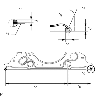
*1 Cylinder Head Gasket *a 7.0 to 9.0 mm (0.276 to 0.354 in.) *b 5.0 to 7.0 mm (0.197 to 0.276 in.) *c 3.0 to 5.0 mm (0.118 to 0.197 in.) *d 166.25 mm (6.55 in.) *e 62.25 mm (2.46 in.) *f Side View *g View A Apply seal packing to a new cylinder head gasket as shown in the illustration.
Seal Packing Toyota Genuine Seal Packing Black, Three Bond 1207 B or equivalent Note
-
Be sure to clean and degrease the contact surfaces.
-
Apply seal packing to the bead on the cylinder head gasket.
-
Install the cylinder head gasket within 3 minutes and tighten the cylinder head set bolts within 15 minutes after applying seal packing.
-
-
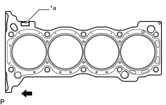
*a Lot No. 
Front Place the cylinder head gasket on the cylinder block surface with the lot No. stamp facing upward.
Note
-
Remove any oil from the contact surface.
-
Make sure that the cylinder head gasket is installed in the correct direction.
-
-
-
INSTALL CYLINDER HEAD SUB-ASSEMBLY
Tech Tips
-
Perform "Inspection After Repairs" after replacing the cylinder head sub-assembly.
-
The cylinder head set bolts are tightened in 3 successive steps.
-
Place the cylinder head sub-assembly on the cylinder block.
Note
-
Make sure that no oil is on the mounting surface of the cylinder head sub-assembly.
-
Place the cylinder head sub-assembly on the cylinder block gently so as not to damage the gasket with the bottom part of the head.
-
-
Install the plate washers to the cylinder head set bolts.
-
Apply a light coat of engine oil to the threads and under the heads of the cylinder head set bolts.
-
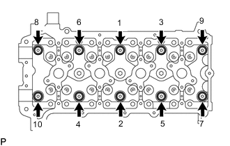
Step 1:
Using several steps, install and uniformly tighten the 10 cylinder head set bolts with plate washers in the sequence shown in the illustration.
- Torque:
- 39 N*m { 398 kgf*cm, 29 ft.*lbf }
-
Mark the front of each cylinder head set bolt head with paint.
-
Step 2:
Tighten the cylinder head set bolts 90° in the sequence shown in step 1.
-
Step 3:
Tighten the cylinder head set bolts another 90° in the sequence shown in step 1.
-
Check that the paint marks are now at a 180° angle to the front.
-
-
CONNECT ENGINE WIRE
-
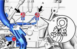
*a INCORRECT *b Do not Allow Wires to Overlap Connect the engine wire to the cylinder head sub-assembly with the 3 bolts so that it is within the specified range shown in the illustration.
- Torque:
- for bolt A
- 25 N*m { 255 kgf*cm, 18 ft.*lbf }
- for bolt B
- 30 N*m { 306 kgf*cm, 22 ft.*lbf }
-
-
INSTALL VALVE STEM CAP
-
Apply a light coat of engine oil to the valve stem ends.
-
Install the 16 valve stem caps to the cylinder head sub-assembly.
Note
Do not drop the valve stem caps into the cylinder head sub-assembly.
-
-
INSTALL VALVE LASH ADJUSTER ASSEMBLY
-
Inspect each valve lash adjuster assembly before installing it.
-
Install the 16 valve lash adjuster assemblies to the cylinder head sub-assembly.
Note
Install each valve lash adjuster assembly to the same place it was removed from.
-
-
INSTALL NO. 1 VALVE ROCKER ARM SUB-ASSEMBLY
-
Apply clean engine oil to the valve lash adjuster assembly tips and valve stem cap surfaces.
-
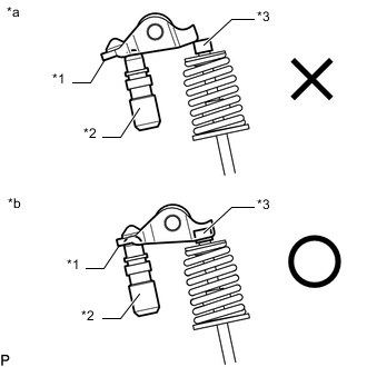
*1 No. 1 Valve Rocker Arm Sub-assembly *2 Valve Lash Adjuster Assembly *3 Valve Stem Cap *a INCORRECT *b CORRECT Install the 16 No. 1 valve rocker arm sub-assemblies as shown in the illustration.
Note
Install the valve stem cap, valve lash adjuster assembly and No. 1 valve rocker arm sub-assembly to the same places they were removed from.
-
-
INSTALL CAMSHAFT
Tech Tips
Perform "Inspection After Repairs" after replacing the camshaft or No. 2 camshaft.
-
Apply clean engine oil to the camshaft cams and cylinder head journals.
-
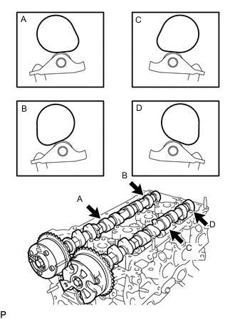
Position the camshaft and No. 2 camshaft as shown in the illustration.
-
*1 No. 1 Valve Rocker Arm Sub-assembly *2 Valve Lash Adjuster Assembly *3 Valve Stem Cap *a INCORRECT *b CORRECT Make sure that the No. 1 valve rocker arm sub-assemblies are installed as shown in the illustration.
-
-
INSTALL CAMSHAFT BEARING CAP
-
Temporarily install the No. 1 camshaft bearing cap.
-
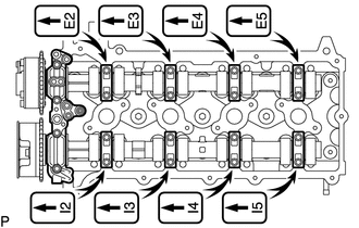
Confirm the location for each No. 2 camshaft bearing cap and install each one to the proper location.
-
Uniformly temporarily install the 20 bolts while keeping the camshaft level.
-
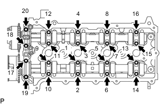
Tighten the 20 bolts in the order shown in the illustration.
- Torque:
- 15.5 N*m { 158 kgf*cm, 11 ft.*lbf }
-
-
INSTALL NO. 1 CHAIN VIBRATION DAMPER
-
INSTALL CHAIN SUB-ASSEMBLY
-
INSTALL CHAIN TENSIONER SLIPPER
-
INSTALL NO. 1 CHAIN TENSIONER ASSEMBLY
-
INSTALL TIMING CHAIN GUIDE
-
CHECK NO. 1 CYLINDER TO TDC/COMPRESSION
-
INSTALL CYLINDER HEAD COVER CONNECTOR SUB-ASSEMBLY
-
INSTALL EXHAUST MANIFOLD
-
INSTALL TIMING CHAIN COVER SUB-ASSEMBLY