CYLINDER HEAD GASKET REMOVAL
CAUTION / NOTICE / HINT
The necessary procedures (adjustment, calibration, initialization, or registration) that must be performed after parts are removed, installed, or replaced during the cylinder head gasket removal/installation are shown below.
| Replacement Part or Procedure | Necessary Procedures | Effects/Inoperative when not Performed | Link |
|---|---|---|---|
| Replacement of ECM |
|
Engine starting | w/o DPF w/ DPF |
for RC61: |
|
||
| Code registration (Immobiliser system) | Engine start function | See the Service Bulletin for the registration method. | |
| Replacement of engine assembly |
|
Engine starting | w/o DPF w/ DPF |
| Clear Crank Time Compensation Data | Engine starting | w/o DPF w/ DPF |
|
| Replacement of crankshaft position sensor plate | Clear Crank Time Compensation Data | Crank time compensation data compensation amount is same as before replacement, affecting crank time compensation data | w/o DPF w/ DPF |
| Replacement of injector assembly |
|
Engine starting | w/o DPF w/ DPF |
|
Perform initialization | - | w/o DPF w/ DPF |
for AC60E: |
Reset memory |
|
|
for AC60E: |
ATF thermal degradation estimate reset | The value of the Data List item "ATF Thermal Degradation Estimate" is not estimated correctly | |
for AC60F: |
Reset memory |
|
|
for AC60F: |
ATF thermal degradation estimate reset | The value of the Data List item "ATF Thermal Degradation Estimate" is not estimated correctly | |
w/ Automatic Headlight Beam Level Control System: |
Headlight leveling ECU assembly initialization | Headlight leveling function | |
for 4WD: |
|
VSC malfunctioning |
CAUTION:
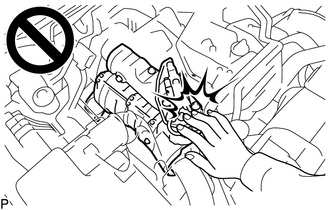
To prevent burns, do not touch the engine, exhaust manifold or other high temperature components while the engine is hot.
Note
-
When replacing the parts in the following chart (A), replace the No. 1 injection pipe sub-assembly, No. 2 injection pipe sub-assembly and/or fuel inlet pipe sub-assembly with new ones.
Replaced Parts (A) Pipes Requiring New Replacement Injector assembly (including shuffling the injector assemblies between the cylinders)
-
No. 1 injection pipe sub-assembly
-
No. 2 injection pipe sub-assembly
-
Supply pump assembly
-
Common rail assembly
-
Cylinder block sub-assembly
-
Cylinder head sub-assembly
-
Cylinder head gasket
-
Timing chain case assembly
-
No. 1 injection pipe sub-assembly
-
No. 2 injection pipe sub-assembly
-
Fuel inlet pipe sub-assembly
-
-
After removing the No. 1 injection pipe sub-assembly, No. 2 injection pipe sub-assembly and/or fuel inlet pipe sub-assembly, clean them with a brush and compressed air.
-
The injector assembly is a precision instrument. Do not use the injector assembly if it is struck or dropped.
-
The supply pump assembly is a precision instrument. Do not use the supply pump assembly if it is struck or dropped.
-
Hold the supply pump assembly itself during removal and installation. Do not hold the pre-stroke control valve or fuel pipe, etc.
-
Make sure foreign matter does not enter the fuel path.
PROCEDURE
-
REMOVE CAMSHAFT
-
REMOVE TIMING CHAIN COVER ASSEMBLY
-
REMOVE NO. 1 VALVE ROCKER ARM SUB-ASSEMBLY
-
REMOVE VALVE LASH ADJUSTER ASSEMBLY
-
REMOVE CYLINDER HEAD SUB-ASSEMBLY
-
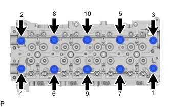
Uniformly loosen the 10 cylinder head set bolts in several passes in the sequence shown in the illustration. Then remove the 10 cylinder head set bolts and 6 cylinder head set bolt spacers.
Note
-
Cylinder head sub-assembly warpage or cracking could result from removing bolts in the incorrect order.
-
Be careful not to drop the cylinder head set bolt spacers into the cylinder head sub-assembly.
-
-
Lift the cylinder head sub-assembly from the ring pins on the cylinder block sub-assembly, and place the cylinder head sub-assembly on wooden blocks on a bench.
Note
Be careful not to damage the contact surfaces of the cylinder head sub-assembly and cylinder block sub-assembly.
Tech Tips
If the cylinder head sub-assembly is difficult to lift, use a screwdriver to pry between the cylinder head sub-assembly and cylinder block sub-assembly.
-
-
REMOVE CYLINDER HEAD GASKET
-
INSPECT CYLINDER HEAD SET BOLT