COMMON RAIL REMOVAL
CAUTION / NOTICE / HINT
CAUTION:
-
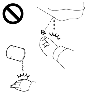
To prevent burns, do not remove the oil pan drain plug and oil filter sub-assembly while the engine is hot.
-

To prevent burns, do not touch the engine, exhaust manifold or other high temperature components while the engine is hot.
Note
-
When replacing the parts in the following chart (A), replace the No. 1 injection pipe sub-assembly, No. 2 injection pipe sub-assembly, No. 3 injection pipe sub-assembly, No. 4 injection pipe sub-assembly and/or fuel inlet pipe sub-assembly with new ones.
-
After removing the No. 1 injection pipe sub-assembly, No. 2 injection pipe sub-assembly, No. 3 injection pipe sub-assembly, No. 4 injection pipe sub-assembly and fuel inlet pipe sub-assembly, clean them with a brush and compressed air.
-
When replacing the common rail assembly, do not remove the foreign object mixing prevention caps of the common rail assembly until just before the No. 1 injection pipe sub-assembly, No. 2 injection pipe sub-assembly, No. 3 injection pipe sub-assembly, No. 4 injection pipe sub-assembly and fuel inlet pipe sub-assembly are connected to the common rail assembly.
Replaced Parts (A) Pipes Requiring New Replacement
-
Injector assembly (including shuffling the injector assemblies between the cylinders)
-
Common rail assembly
-
Cylinder head sub-assembly
-
No. 1 injection pipe sub-assembly
-
No. 2 injection pipe sub-assembly
-
No. 3 injection pipe sub-assembly
-
No. 4 injection pipe sub-assembly
-
Supply pump assembly
-
Common rail assembly
-
Cylinder block sub-assembly
-
Cylinder head sub-assembly
-
Cylinder head gasket
-
Timing Gear Case Assembly
Fuel inlet pipe sub-assembly -
PROCEDURE
-
PRECAUTION
Note
After turning the ignition switch off, waiting time may be required before disconnecting the cable from the battery terminal. Therefore, make sure to read the disconnecting the cable from the battery terminal notice before proceeding with work.
-
DISCONNECT CABLE FROM NEGATIVE BATTERY TERMINAL
Note
When disconnecting the cable, some systems need to be initialized after the cable is reconnected.
-
REMOVE NO. 1 ENGINE UNDER COVER ASSEMBLY
-
REMOVE NO. 2 ENGINE UNDER COVER
-
DRAIN ENGINE OIL
-
REMOVE NO. 1 INTAKE PIPE
-
REMOVE MANIFOLD STAY
-
REMOVE OIL FILTER SUB-ASSEMBLY
-
REMOVE NO. 1, NO. 2 AND NO. 3 INJECTION PIPE SUB-ASSEMBLY
-
REMOVE NO. 4 INJECTION PIPE SUB-ASSEMBLY
-
REMOVE NO. 2 NOZZLE LEAKAGE PIPE ASSEMBLY
-
REMOVE ENGINE OIL LEVEL DIPSTICK GUIDE
-
REMOVE FUEL INLET PIPE SUB-ASSEMBLY
-
REMOVE COMMON RAIL ASSEMBLY
-
Disconnect the connector from the pressure discharge valve.
-
Disconnect the connector from the fuel pressure sensor connector.
-
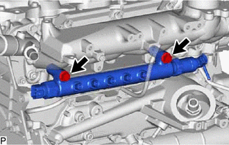
Remove the 2 bolts, common rail assembly from the cylinder head sub-assembly.
Note
Do not remove the pressure discharge valve or fuel pressure sensor from the common rail assembly.
-