ECD SYSTEM(w/ Urea SCR System), Diagnostic DTC:P0335, P0339
| DTC Code | DTC Name |
|---|---|
| P0335 | Crankshaft Position Sensor "A" Circuit |
| P0339 | Crankshaft Position Sensor "A" Circuit Intermittent |
DESCRIPTION
The crankshaft position sensor system consists of a crank angle sensor plate and Magneto-Resistive Element (MRE) type sensor. The crank angle sensor plate has 34 teeth at 10° intervals (2 teeth are missing for detecting top dead center), and is installed on the crankshaft. The crankshaft position sensor generates 34 signals per crankshaft revolution. The ECM uses the NE signal to detect the crankshaft position and engine speed.
| DTC No. | Detection Item | DTC Detection Condition | Trouble Area | MIL | Memory |
|---|---|---|---|---|---|
| P0335 | Crankshaft Position Sensor "A" Circuit | Either of the following conditions is met (1 trip detection logic):
Tech Tips When the engine is stopped and started automatically due to stop and start system control, the crankshaft position sensor does not monitor during the automatic cranking. |
|
Comes on | DTC stored |
| P0339 | Crankshaft Position Sensor "A" Circuit Intermittent | Under conditions (a), (b) and (c), no crankshaft position sensor signal is sent to the ECM for 0.05 seconds or more (1 trip detection logic):
Tech Tips When the engine is stopped and started automatically due to stop and start system control, the crankshaft position sensor does not monitor during the automatic cranking. |
|
- | DTC stored |
| DTC No. | Data List |
|---|---|
| P0335 P0339 |
Engine Speed |
Tech Tips
-
If DTC P0335 and/or P0339 is stored, the following symptoms may appear:
-
Difficulty starting
-
Misfire
-
Combustion noise
-
Black smoke
-
White smoke
-
Lack of power
Reference: Inspection using an oscilloscope.
The correct waveform is as shown.
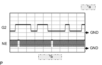
| *a | 2 V/DIV. |
| *b | 20 msec./DIV. |
| ECM Terminal Name | Between G2+ and G2- Between NE+ and NE- |
| Tester Range | 2 V/DIV., 20 msec./DIV. |
| Condition | Idling with warm engine |
MONITOR DESCRIPTION
If there is no signal from the crankshaft position sensor despite the crankshaft revolving, the ECM interprets this as a malfunction of the sensor.
CONFIRMATION DRIVING PATTERN
| DTC No. | DTC Detection Drive Pattern |
|---|---|
| P0335 | Crank or start engine |
| P0339 | Engine running at 1000 rpm or higher with vehicle stationary |
WIRING DIAGRAM
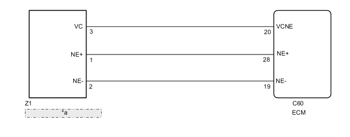
| *a | Crankshaft Position Sensor |
CAUTION / NOTICE / HINT
Note
After replacing the ECM, the new ECM needs registration (Click here ) and initialization Click here.
Tech Tips
-
If no problem is found by this diagnostic troubleshooting procedure, check for problems by referring to the engine mechanical section.
-
The engine speed can be checked by using the GTS. To perform the check, follow the procedures below:
-
Connect the GTS to the DLC3.
-
Start the engine.
-
Turn the GTS on.
-
Enter the following menus: Powertrain / Engine / Data List / Primary / Engine Speed.
-
The engine speed may be indicated as zero despite the engine running normally. This is caused by a lack of NE signals from the crankshaft position sensor. Alternatively, the engine speed may be indicated as lower than the actual engine speed if the crankshaft position sensor output voltage is insufficient.
-
Read freeze frame data using the GTS. Freeze frame data records the engine condition when malfunctions are detected. When troubleshooting, freeze frame data can help determine if the vehicle was moving or stationary, if the engine was warmed up or not, and other data from the time the malfunction occurred.
PROCEDURE
-
CHECK ENGINE CRANKING CONDITION
-
Check the engine cranking condition.
Result Result Proceed to Cranking is OK. A Does not crank at all.* B Tech Tips
*: When the engine cannot crank, there may be a malfunction in the starter assembly.
B 
GO TO PROBLEM SYMPTOMS TABLE (ENGINE DOES NOT CRANK (DOES NOT START)) Click here
A 
-
-
READ VALUE USING GTS (ENGINE SPEED)
-
Connect the GTS to the DLC3.
-
Turn the ignition switch to ON.
-
Turn the GTS on.
-
Enter the following menus: Powertrain / Engine / Data List / Primary / Engine Speed.
-
Start the engine.
-
Read the values displayed on the GTS while the engine is running.
Powertrain > Engine > Data ListTester Display Engine Speed Standard Correct values are displayed. Tech Tips
-
To check the engine speed change, display the graph on the GTS.
-
If the engine does not start, check the engine speed while cranking.
-
If the engine speed indicated on the GTS remains at zero (0), there may be an open or short in the crankshaft position sensor circuit.
Result Proceed to OK NG -
NG 
INSPECT ECM (CRANKSHAFT POSITION SENSOR) Click here
OK
-
-
CHECK WHETHER DTC OUTPUT RECURS (DTC P0335 AND/OR P0339)
-
Connect the GTS to the DLC3.
-
Turn the ignition switch to ON.
-
Turn the GTS on.
-
Clear the DTCs.
Powertrain > Engine > Clear DTCs -
Turn the ignition switch off and wait for at least 30 seconds.
-
Start the engine and run it at 1000 rpm or higher for 5 seconds or more.
-
Enter the following menus: Powertrain / Engine / Trouble Codes.
-
Read the DTCs.
Powertrain > Engine > Trouble CodesResult Result Proceed to DTC is not output A DTC P0335 and/or P0339 is output B
A
CHECK FOR INTERMITTENT PROBLEMS Click here
B
-
-
INSPECT ECM (CRANKSHAFT POSITION SENSOR)
-
Inspect the ECM using an oscilloscope.
-
While the engine is idling, check the waveform between the terminals of the ECM connector.
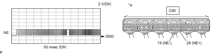
*a Component with harness connected
(ECM)
- - OK Tester Connection Tester Range Condition Specified Condition C60-28 (NE+) - C60-19 (NE-) 2 V/DIV.
50 msec./DIV.
Cranking to idling Correct waveform as shown in illustration
Result Proceed to OK NG -
OK
REPLACE ECM Click here
NG
-
-
CHECK SENSOR INSTALLATION (CRANKSHAFT POSITION SENSOR)
-
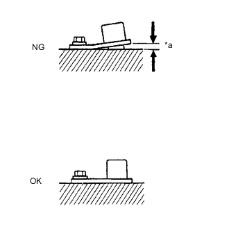
*a Clearance Check the crankshaft position sensor installation condition.
OK Crankshaft position sensor is installed correctly. Result Proceed to OK NG
NG
SECURELY REINSTALL CRANKSHAFT POSITION SENSOR Click here
OK
-
-
INSPECT CRANKSHAFT (TEETH OF SENSOR PLATE)
-
Inspect the teeth of the crank angle sensor plate.
OK Crank angle sensor plate does not have any cranks or deformation. Result Proceed to OK NG
NG
REPLACE CRANKSHAFT Click here
OK
-
-
REPLACE CRANKSHAFT POSITION SENSOR
-
Replace the crankshaft position sensor.
Result Proceed to NEXT
NEXT
-
-
CONFIRM WHETHER MALFUNCTION HAS BEEN SUCCESSFULLY REPAIRED
-
Connect the GTS to the DLC3.
-
Turn the ignition switch to ON.
-
Turn the GTS on.
-
Clear the DTCs.
Powertrain > Engine > Clear DTCs -
Turn the ignition switch off for 30 seconds or more.
-
Start the engine and run it at 1000 rpm or higher for 5 seconds or more.
-
Enter the following menus: Powertrain / Engine / Trouble Codes.
-
Confirm that the DTC is not output.
Powertrain > Engine > Trouble CodesResult Proceed to NEXT
NEXT
END
-
-
REPLACE CRANKSHAFT
-
Replace the crankshaft.
Result Proceed to NEXT
NEXT
GO TO STEP 8 Click here
-
-
SECURELY REINSTALL CRANKSHAFT POSITION SENSOR
-
Securely reinstall the crankshaft position sensor.
Result Proceed to NEXT
NEXT
GO TO STEP 8 Click here
-
-
REPLACE ECM
-
Replace the ECM.
Result Proceed to NEXT
NEXT
GO TO STEP 8 Click here
-