HYBRID CONTROL SYSTEM, Diagnostic DTC:P1E15-450, P1E17-450
| DTC Code | DTC Name |
|---|---|
| P1E15-450 | FC Stack Positive Relay Stuck Closed |
| P1E17-450 | FC Stack Negative Relay Stuck Closed |
DTC SUMMARY
-
MALFUNCTION DESCRIPTION
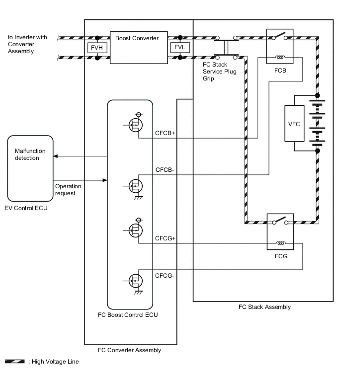
The EV control ECU compares the FC converter voltage before boosting (FVL) and the FC stack voltage (VFC), at the time an FC relay open command is output, and determines whether any high-voltage relays (FC relays) built inside the FC stack assembly is stuck.
The cause of this malfunction may be one of the following:
-
Voltage sensor (FVL) malfunction
-
FC boost control ECU malfunction
FC converter assembly built in voltage pressure sensor (FVL) system malfunction
-
FC stack assembly (FC relay) malfunction
High voltage system malfunction
-
FC boost control ECU malfunction
FC relay low voltage (excitation line) system malfunction
-
DESCRIPTION
The FC relay connects and disconnects the high-voltage FC stack circuit.
The FC relays are provided each on the positive (+) terminal (FCB) and negative (-) terminal (FCG) of the high-voltage circuit inside the FC stack assembly, and the relays operate on the excitation signal which is sent from the FC boost control ECU. The excitation signal is output when the FC boost control ECU receives a request from the EV control ECU.
The EV control ECU compares the FC converter voltage before boosting (FVL) and the FC stack voltage (VFC) under the following power switch operation conditions and determines whether the circuit is stuck or malfunctioning.
-
When the power switch is turned off (not on READY): Detection of stuck FC relay on one terminal
-
When the power switch is turned on (IG): Detection of stuck FC relay on both terminals
For high voltage wiring diagrams, refer to the system description.
| DTC No. | Detection Item | DTC Detection Condition | Trouble Area | Warning Indicate |
|---|---|---|---|---|
| P1E15-450 | FC Stack Positive Relay Stuck Closed | FC relay on positive (+) terminal (FCB) is stuck.
FC relays on positive (+) terminal (FCB) and negative (-) terminal (FCG) are both stuck.
(1 trip detection logic) |
|
Master Warning Light: Comes on |
| P1E17-450 | FC Stack Negative Relay Stuck Closed | FC relay on positive (-) terminal (FCG) is stuck.
(1 trip detection logic) |
|
Master Warning Light: Comes on |
| DTC No. | System | Data List |
|---|---|---|
| P1E15-450 P1E17-450 |
EV |
|
| FC | FC Total Voltage |
CAUTION / NOTICE / HINT
CAUTION:
-


Before the following operations are conducted, take precautions to prevent electric shock by turning the power switch off, wearing insulated gloves, and removing the service plug grips from both FC stack assembly and EV battery.
-
Inspecting the high-voltage system
-
Disconnecting the low voltage connector of the inverter with converter assembly
-
Disconnecting the low voltage connector of the EV battery
-
Disconnecting the low voltage connector of the FC stack assembly
-
Disconnecting the low voltage connector of the FC converter assembly
Tech Tips
No removal order is specified for the service plug grips of the FC stack assembly and EV battery.
-

After removing the service plug grip from the EV battery, put it in your pocket to prevent other technicians from accidentally reconnecting it while you are working on the high-voltage system. After removing the service grip from the FC stack assembly, store it in a safe location and use the "HIGH-VOLTAGE, DO NOT TOUCH" sign to notify other technicians that you are working on the high-voltage system.
-

*a Without waiting for 10 minutes After removal of the service plug grips of both FC stack assembly and EV battery, wait for at least 10 minutes before touching the high-voltage connectors and terminals. After waiting for 10 minutes, check the voltage at the terminals in the inspection point in the inverter with converter assembly. The voltage should be 0 V before beginning work.
Tech Tips
At least 10 minutes are necessary to discharge the high-voltage capacitors inside the inverter with converter assembly and FC stack assembly.
Note
-
After turning the power switch off, waiting time may be required before disconnecting the cable from the negative (-) auxiliary battery terminal. Therefore, make sure to read the disconnecting the cable from the negative (-) auxiliary battery terminal notices before proceeding with work.
-
When reinstalling the service plug grip to the FC stack assembly or the EV battery, slide the lever of the service plug until the letters "UNLOCK" are completely hidden, and insert it firmly.
-
When the vehicle is parked with the power switch off, if the FC control ECU judges that the FC stack temperature will go below 0°C (32°F), it activates the FC air compressor, hydrogen pump and FC cooling water pump for a maximum of 180 seconds and drains water from the FC stack assembly. When performing inspection or repairs with the power switch off (not on (IG) or on (READY)), disconnect the cable from the negative (-) auxiliary battery terminal before performing work (If the auxiliary battery voltage is needed to conduct inspection, warm up the FC system beforehand).
Tech Tips
-
DTC P1E15-450 is output, and when the following malfunction condition is met, the power switch will not be able to be turned on (READY).
-
The FC relays on both terminals are detected to be stuck.
-
After the repair, clear the DTCs and perform the following procedure to check that DTCs are not output.
-
Turn the power switch off and wait for 3 minutes or more.
-
Turn the power switch on (IG) and wait for 30 seconds.
-
Turn the power switch on (READY) and wait for 30 seconds or more.
-
Turn the power switch off and wait for 3 minutes or more.
PROCEDURE
-
CHECK DTC OUTPUT (EV)
-
Connect the GTS to the DLC3.
-
Turn the power switch on (IG).
-
Enter the following menus: Powertrain / EV / Trouble Codes.
-
Check for DTCs.
Powertrain > EV > Trouble CodesResult Result Proceed to P1E15-450 is output. A P1E17-450 is output. B -
Turn the power switch off.
B 
CHECK DTC OUTPUT (EV) Click here
A 
-
-
CHECK DTC OUTPUT (EV)
-
Connect the GTS to the DLC3.
-
Turn the power switch on (IG).
-
Enter the following menus: Powertrain / EV / Trouble Codes.
-
Check for DTCs.
Powertrain > EV > Trouble CodesResult Result Proceed to P1E15-450 only is output, or DTCs except the ones in the tables below are also output. A Any of the following DTCs including pending DTCs are also output. B Malfunction Content Relevant DTC Microcomputer malfunction P0A1B-163, 164, 168, 193, 511, 512, 661, 786, 794, 795, 796 Drive Motor "A" Control Module P0A1D-148 EV Control Module P1D8F-474, 475, 476, 477, 479, 481, 482, 483, 484 FC Air Compressor Motor "A" Control Module P324E-788 Motor CPU Power Relay Sense Circuit Intermittent No Continuity Power source circuit malfunction P2511-149 EV CPU Power Relay Sense Circuit Intermittent No Continuity Communication system malfunction U0110 (all INF codes)*1 Lost Communication with Drive Motor Control Module "A" U1160-450 Lost Communication with FCDC System U1161-450 Lost Communication with FC System Sensor and actuator circuit malfunction P0A3F-243 Drive Motor "A" Position Sensor Circuit P0A40-500 Drive Motor "A" Position Sensor Circuit Range/Performance P0A41-245 Drive Motor "A" Position Sensor Circuit Low P0ADC-226 Battery Positive Contactor Control Circuit High P0AE0-450 Battery Negative Contactor Control Circuit High P0AE7-450 Battery Precharge Contactor Control Circuit High P0AA1-233 Battery Positive Contactor Circuit Stuck Closed P1D75-450 FC Air Compressor Motor "A" Position Sensor Circuit P1D76-450 FC Air Compressor Motor "A" Position Sensor Circuit Range/Performance P1D77-450 FC Air Compressor Motor "A" Position Sensor Circuit Low P0A78-266, 267, 586 Drive Motor "A" Inverter Performance P0A94-442, 585 Boosting Converter Performance P0C76-523 EV Battery System Discharge Time Too Long System malfunction P3004-132 High Voltage Power Resource P0AA6-458, 486, 487, 488, 526, 611, 612, 613, 614 EV Battery Voltage System Isolation Fault Tech Tips
-
*1: If any INF codes are output for this DTC, refer to the corresponding diagnostic procedure.
-
P1E15-450 may be output as a result of the malfunction indicated by the DTCs above.
-
The chart above is listed in inspection order of priority.
-
Check DTCs that are output at the same time by following the listed order. (The main cause of the malfunction can be determined without performing unnecessary inspections.)
-
-
Turn the power switch off.
A
GO TO STEP 4 Click here
B 
GO TO DTC CHART (EV CONTROL SYSTEM)
-
-
CHECK DTC OUTPUT (EV)
-
Connect the GTS to the DLC3.
-
Turn the power switch on (IG).
-
Enter the following menus: Powertrain / EV / Trouble Codes.
-
Check for DTCs.
Powertrain > EV > Trouble CodesResult Result Proceed to P1E17-450 only is output, or DTCs except the ones in the tables below are also output. A Any of the following DTCs including pending DTCs are also output. B Malfunction Content Relevant DTC Microcomputer malfunction P0A1B-163, 164, 168, 193, 511, 512, 661, 786, 794, 795, 796 Drive Motor "A" Control Module P0A1D-148 EV Control Module P1D8F-474, 475, 476, 477, 479, 481, 482, 483, 484 FC Air Compressor Motor "A" Control Module P324E-788 Motor CPU Power Relay Sense Circuit Intermittent No Continuity Power source circuit malfunction P2511-149 EV CPU Power Relay Sense Circuit Intermittent No Continuity Communication system malfunction U0110 (all INF codes)*1 Lost Communication with Drive Motor Control Module "A" U1160-450 Lost Communication with FCDC System U1161-450 Lost Communication with FC System Sensor and actuator circuit malfunction P0A3F-243 Drive Motor "A" Position Sensor Circuit P0A40-500 Drive Motor "A" Position Sensor Circuit Range/Performance P0A41-245 Drive Motor "A" Position Sensor Circuit Low P1D75-450 FC Air Compressor Motor "A" Position Sensor Circuit P1D76-450 FC Air Compressor Motor "A" Position Sensor Circuit Range/Performance P1D77-450 FC Air Compressor Motor "A" Position Sensor Circuit Low P0A78-266, 267, 586 Drive Motor "A" Inverter Performance P0A94-442, 585 Boosting Converter Performance P0C76-523 EV Battery System Discharge Time Too Long System malfunction P3004-132 High Voltage Power Resource P0AA6-458, 486, 487, 488, 526, 611, 612, 613, 614 EV Battery Voltage System Isolation Fault Tech Tips
-
*1: If any INF codes are output for this DTC, refer to the corresponding diagnostic procedure.
-
P1E17-450 may be output as a result of the malfunction indicated by the DTCs above.
-
The chart above is listed in inspection order of priority.
-
Check DTCs that are output at the same time by following the listed order. (The main cause of the malfunction can be determined without performing unnecessary inspections.)
-
-
Turn the power switch off.
B
GO TO DTC CHART (HYBRID CONTROL SYSTEM) Click here
A
-
-
CHECK DTC OUTPUT (FCDC)
-
Connect the GTS to the DLC3.
-
Turn the power switch on (IG).
-
Enter the following menus: Powertrain / FCDC / Trouble Codes.
-
Check for DTCs.
Powertrain > FCDC > Trouble CodesResult Result Proceed to None of the following DTCs are output. A Any of the following DTCs are also output. B Malfunction Content Relevant DTC Sensor and actuator circuit malfunction P1D0E-450 FVH (FC Converter Output Voltage)/VH Voltage Correlation P1D0F-450 FVC (Cell Monitor Voltage)/FVL (FC Converter Input Voltage) Correlation P1D1D-450 FVH (FC Converter Output Voltage)/Over Voltage Tech Tips
P1E15-450 and P1E17-450 may be output as a result of the malfunction indicated by the DTCs above.
-
Turn the power switch off.
B
GO TO DTC CHART (FC BOOST CONTROL SYSTEM) Click here
A
-
-
CHECK DTC OUTPUT (FC)
-
Connect the GTS to the DLC3.
-
Turn the power switch on (IG).
-
Enter the following menus: Powertrain / FC / Trouble Codes.
-
Check for DTCs.
Powertrain > FC > Trouble CodesResult Result Proceed to None of the following DTCs are output. A Any of the following DTCs are also output. B Malfunction Content Relevant DTC Sensor and actuator circuit malfunction P1D5F-450 Lost Communication with Cell Monitor P1DCF-450 Cell Monitor Performance Tech Tips
P1E15-450 and P1E17-450 may be output as a result of the malfunction indicated by the DTCs above.
-
Turn the power switch off and wait for 3 minutes or more.
B
GO TO DTC CHART (FC CONTROL SYSTEM) Click here
A
-
-
CLEAR DTC
-
Connect the GTS to the DLC3.
-
Turn the power switch on (IG).
-
Enter the following menus: Powertrain / EV / Trouble Codes.
-
Read and record the DTCs and freeze frame data.
Powertrain > EV > Trouble Codes -
Clear the DTCs and freeze frame data.
Powertrain > EV > Clear DTCs -
Turn the power switch off and wait for 3 minutes or more.
Result Proceed to NEXT
NEXT
-
-
CHECK DTC OUTPUT (EV)
-
Connect the GTS to the DLC3.
-
Turn the power switch off and wait for 3 minutes or more.
-
Turn the power switch on (IG) and wait for 30 seconds or more.
-
Turn the power switch on (READY) and wait for 30 seconds or more.
-
Turn the power switch off and wait for 3 minutes or more.
-
Turn the power switch on (IG).
-
Enter the following menus: Powertrain / EV / Trouble Codes.
-
Check for DTCs.
Powertrain > EV > Trouble CodesResult Result Proceed to P1E15-450 or P1E17-450 is output again. A Neither P1E15-450 or P1E17-450 is output again. B -
Turn the power switch off.
A
REPLACE FC STACK ASSEMBLY Click here
B
CHECK INTERMITTENT PROBLEMS
-