HYBRID CONTROL SYSTEM, Diagnostic DTC:P1D8F-479, P1D8F-483, P1D8F-484
| DTC Code | DTC Name |
|---|---|
| P1D8F-479 | FC Air Compressor Motor "A" Control Module |
| P1D8F-483 | FC Air Compressor Motor "A" Control Module |
| P1D8F-484 | FC Air Compressor Motor "A" Control Module |
DESCRIPTION
The MG ECU, which is built into the inverter with converter assembly, monitors its internal operation and detects the following malfunctions.
| DTC No. | Detection Item | DTC Detection Condition | Trouble Area | Warning Indicate |
|---|---|---|---|---|
| P1D8F-479 | FC Air Compressor Motor "A" Control Module | FC air compressor motor resolver angle malfunction: The difference between the resolver angle for control and estimated resolver angle exceeds the allowable limit. (1 trip detection logic) |
|
Master Warning Light: Comes on |
| P1D8F-483 | FC Air Compressor Motor "A" Control Module | FC air compressor motor resolver REF signal cycle malfunction: Excitation signal (REF signal) for resolver angle detection cycle malfunction. (1 trip detection logic) |
|
Master Warning Light: Comes on |
| P1D8F-484 | FC Air Compressor Motor "A" Control Module | FC air compressor motor resolver REF signal oscillation stop malfunction: An error is detected when the excitation signal (REF signal) for resolver angle detection is not detected. (1 trip detection logic) |
|
Master Warning Light: Comes on |
| DTC No. | Data List |
|---|---|
| P1D8F-479 | FC Air Compressor Revolution |
| P1D8F-483 | |
| P1D8F-484 |
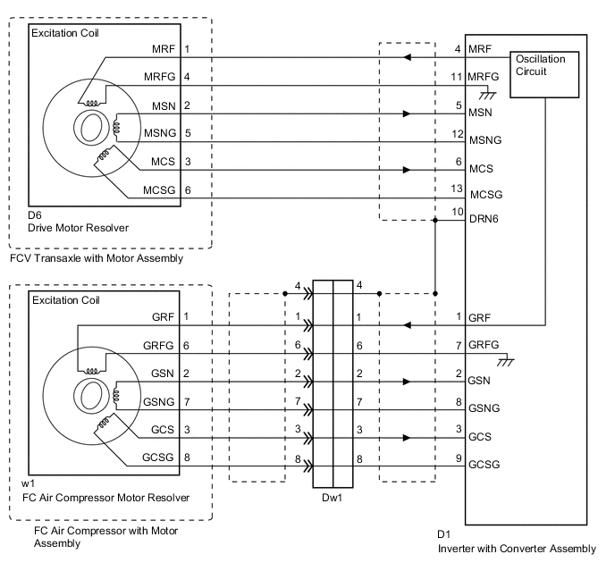
WIRING DIAGRAM
CAUTION / NOTICE / HINT
CAUTION:
-


Before the following operations are conducted, take precautions to prevent electric shock by turning the power switch off, wearing insulated gloves, and removing the service plug grips from both FC stack assembly and EV battery.
-
Inspecting the high-voltage system
-
Disconnecting the low voltage connector of the inverter with converter assembly
-
Disconnecting the low voltage connector of the EV battery
-
Disconnecting the low voltage connector of the FC stack assembly
-
Disconnecting the low voltage connector of the FC converter assembly
Tech Tips
No removal order is specified for the service plug grips of the FC stack assembly and EV battery.
-

After removing the service plug grip from the EV battery, put it in your pocket to prevent other technicians from accidentally reconnecting it while you are working on the high-voltage system. After removing the service grip from the FC stack assembly, store it in a safe location and use the "HIGH-VOLTAGE, DO NOT TOUCH" sign to notify other technicians that you are working on the high-voltage system.
-

*a Without waiting for 10 minutes After removal of the service plug grips of both FC stack assembly and EV battery, wait for at least 10 minutes before touching the high-voltage connectors and terminals. After waiting for 10 minutes, check the voltage at the terminals in the inspection point in the inverter with converter assembly. The voltage should be 0 V before beginning work.
Tech Tips
At least 10 minutes are necessary to discharge the high-voltage capacitors inside the inverter with converter assembly and FC stack assembly.
Note
-
After turning the power switch off, waiting time may be required before disconnecting the cable from the negative (-) auxiliary battery terminal. Therefore, make sure to read the disconnecting the cable from the negative (-) auxiliary battery terminal notices before proceeding with work.
-
When reinstalling the service plug grip to the FC stack assembly or the EV battery, slide the lever of the service plug until the letters "UNLOCK" are completely hidden, and insert it firmly.
-
When the vehicle is parked with the power switch off, if the FC control ECU judges that the FC stack temperature will go below 0°C (32°F), it activates the FC air compressor, hydrogen pump and FC cooling water pump for a maximum of 180 seconds and drains water from the FC stack assembly. When performing inspection or repairs with the power switch off (not on (IG) or on (READY)), disconnect the cable from the negative (-) auxiliary battery terminal before performing work (If the auxiliary battery voltage is needed to conduct inspection, warm up the FC system beforehand).
Tech Tips
After the repair, clear the DTCs and perform the following procedure to check that DTCs are not output.
-
Turn the power switch on (IG) and wait for 5 seconds or more.*
-
Connect the GTS to the DLC3.
-
Enter the following menus: Powertrain / FC / Data List / FC Mode, FC Intermittent Operation.
-
Move the shift lever to P, turn the power switch on (READY) and wait until the FC system is started. Waiting for at least 2 minutes is required after turning the power switch on (READY).
-
FC system is started: "FC Working" is displayed for the Data List (FC) item "FC Mode" and "FC Intermittent Operation" is OFF.
-
With the FC system operating, wait for 15 seconds or more.
-
Drive the vehicle forward with the shift lever in D for 5 m (16 ft.) or more.
-
Drive the vehicle backward with the shift lever in R for 5 m (16 ft.) or more.
-
*: Lightly wiggle the connectors and wire harnesses up and down and right and left.
Note
If excessive pressure is applied while the connectors and wire harnesses are wiggled, they may be damaged. After the inspection, make sure to return the wire harnesses and clamps to their original position.
PROCEDURE
-
CHECK DTC OUTPUT (EV)
-
Connect the GTS to the DLC3.
-
Turn the power switch on (IG).
-
Enter the following menus: Powertrain / EV / Trouble Codes.
-
Check for DTCs.
Powertrain > EV > Trouble CodesResult Result Proceed to P1D8F-479, 483 or 484 only is output, or DTCs except the ones in the table below are also output. A Any of the following DTCs are also output. B Relevant DTC P0A3F-243 Drive Motor "A" Position Sensor Circuit P1D75-450 FC Air Compressor Motor "A" Position Sensor Circuit P1D76-450 FC Air Compressor Motor "A" Position Sensor Circuit Range/Performance P1D77-450 FC Air Compressor Motor "A" Position Sensor Circuit Low -
Turn the power switch off.
B 
GO TO DTC CHART Click here
A 
-
-
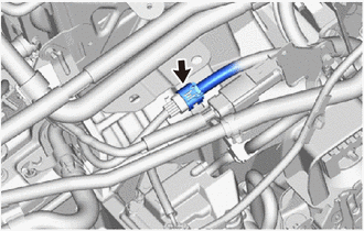
CHECK CONNECTOR CONNECTION CONDITION (INVERTER WITH CONVERTER ASSEMBLY CONNECTOR)
Result Result Proceed to OK A NG (The connector is not connected securely.) B NG (The terminals are not making secure contact or are deformed, or water or foreign matter exists in the connector.) C CAUTION:
Be sure to wear insulated gloves.
-
Check that the service plug grip is not installed to FC stack assembly and EV battery.
Note
After removing the service plug grip, do not turn the power switch on (READY), unless instructed by the repair manual because this may cause a malfunction.
-
Check the connection condition of the low voltage connector of the inverter with converter assembly and the contact pressure of each terminal. Check the terminals for deformation, and check the connector for water ingress and foreign matter.
Note
Before disconnecting the connector, confirm that it is properly connected by checking that the locking claws are engaged and that the connector does not pull out.
OK - The connector is connected securely. - The terminals are not deformed and are connected securely. - No water or foreign matter in the connector. Result Result Proceed to OK A NG (The connector is not connected securely.) B NG (The terminals are not making secure contact or are deformed, or water or foreign matter exists in the connector.) C
B
CONNECT SECURELY
C
REPAIR OR REPLACE HARNESS OR CONNECTOR
A
-
-
CHECK HARNESS AND CONNECTOR (INVERTER WITH CONVERTER ASSEMBLY - FC AIR COMPRESSOR MOTOR RESOLVER)
CAUTION:
Be sure to wear insulated gloves.
-
Check that the service plug grip is not installed to FC stack assembly and EV battery.
Note
After removing the service plug grip, do not turn the power switch on (READY), unless instructed by the repair manual because this may cause a malfunction.
-
Disconnect the inverter with converter assembly connector.
-
Connect the cable to the negative (-) auxiliary battery terminal.
-
Turn the power switch on (IG).
-

*a Front view of wire harness connector
(to Inverter with Converter Assembly)
Measure the voltage according to the value(s) in the table below.
Standard Voltage Tester Connection Condition Specified Condition D1-1 (GRF) - Body ground Power switch on (IG) Below 1 V D1-7 (GRFG) - Body ground Power switch on (IG) Below 1 V D1-2 (GSN) - Body ground Power switch on (IG) Below 1 V D1-8 (GSNG) - Body ground Power switch on (IG) Below 1 V D1-3 (GCS) - Body ground Power switch on (IG) Below 1 V D1-9 (GCSG) - Body ground Power switch on (IG) Below 1 V Note
Turning the power switch on (IG) with the inverter with converter assembly disconnected causes other DTCs to be stored. Clear the DTCs after performing this inspection.
-
Turn the power switch off.
-
Disconnect the cable from the negative (-) auxiliary battery terminal.
-
Reconnect the inverter with converter assembly connector.
Result Proceed to OK NG
NG
REPAIR OR REPLACE HARNESS OR CONNECTOR
OK
-
-
CHECK FC AIR COMPRESSOR MOTOR RESOLVER
CAUTION:
Be sure to wear insulated gloves.
-
Check that the service plug grip is not installed to FC stack assembly and EV battery.
Note
After removing the service plug grip, do not turn the power switch on (READY), unless instructed by the repair manual because this may cause a malfunction.
-
Disconnect the inverter with converter assembly connector.
-
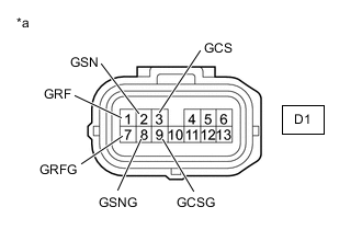
*a Front view of wire harness connector
(to Inverter with Converter Assembly)
Measure the resistance according to the value(s) in the table below.
Standard Resistance Tester Connection Condition Specified Condition D1-1 (GRF) - D1-7 (GRFG) Power switch off 6.5 to 21.5 Ω D1-2 (GSN) - D1-8 (GSNG) Power switch off 10 to 37.5 Ω D1-3 (GCS) - D1-9 (GCSG) Power switch off 9 to 35.5 Ω D1-1 (GRF) or D1-7 (GRFG) - Body ground and other terminals Power switch off 1 MΩ or higher D1-2 (GSN) or D1-8 (GSNG) - Body ground and other terminals Power switch off 1 MΩ or higher D1-3 (GCS) or D1-9 (GCSG) - Body ground and other terminals Power switch off 1 MΩ or higher -
Reconnect the inverter with converter assembly connector.
Result Proceed to OK NG
NG 
CHECK CONNECTOR CONNECTION CONDITION (FC AIR COMPRESSOR REVOLUTION SENSOR WIRE) Click here
OK
-
-
CHECK HARNESS AND CONNECTOR (INVERTER WITH CONVERTER ASSEMBLY - DRIVE MOTOR RESOLVER)
CAUTION:
Be sure to wear insulated gloves.
-
Check that the service plug grip is not installed to FC stack assembly and EV battery.
Note
After removing the service plug grip, do not turn the power switch on (READY), unless instructed by the repair manual because this may cause a malfunction.
-
Disconnect the inverter with converter assembly connector.
-
Connect the cable to the negative (-) auxiliary battery terminal.
-
Turn the power switch on (IG).
-

*a Front view of wire harness connector
(to Inverter with Converter Assembly)
Measure the voltage according to the value(s) in the table below.
Standard Voltage Tester Connection Condition Specified Condition D1-4 (MRF) - Body ground Power switch on (IG) Below 1 V D1-11 (MRFG) - Body ground Power switch on (IG) Below 1 V D1-5 (MSN) - Body ground Power switch on (IG) Below 1 V D1-12 (MSNG) - Body ground Power switch on (IG) Below 1 V D1-6 (MCS) - Body ground Power switch on (IG) Below 1 V D1-13 (MCSG) - Body ground Power switch on (IG) Below 1 V Note
Turning the power switch on (IG) with the inverter with converter assembly disconnected causes other DTCs to be stored. Clear the DTCs after performing this inspection.
-
Turn the power switch off.
-
Disconnect the cable from the negative (-) auxiliary battery terminal.
-
Reconnect the inverter with converter assembly connector.
Result Proceed to OK NG
NG
REPAIR OR REPLACE HARNESS OR CONNECTOR
OK
-
-
CHECK DRIVE MOTOR RESOLVER
CAUTION:
Be sure to wear insulated gloves.
-
Check that the service plug grip is not installed to FC stack assembly and EV battery.
Note
After removing the service plug grip, do not turn the power switch on (READY), unless instructed by the repair manual because this may cause a malfunction.
-
Disconnect the inverter with converter assembly connector.
-
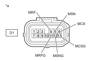
*a Front view of wire harness connector
(to Inverter with Converter Assembly)
Measure the resistance according to the value(s) in the table below.
Standard Resistance Tester Connection Condition Specified Condition D1-4 (MRF) - D1-11 (MRFG) Power switch off 5.8 to 11.8 Ω D1-5 (MSN) - D1-12 (MSNG) Power switch off 11.7 to 17.7 Ω D1-6 (MCS) - D1-13 (MCSG) Power switch off 11.7 to 17.7 Ω D1-4 (MRF) or D1-11 (MRFG) - Body ground and other terminals Power switch off 1 MΩ or higher D1-5 (MSN) or D1-12 (MSNG) - Body ground and other terminals Power switch off 1 MΩ or higher D1-6 (MCS) or D1-13 (MCSG) - Body ground and other terminals Power switch off 1 MΩ or higher -
Reconnect the inverter with converter assembly connector.
Result Proceed to OK NG
NG
CHECK CONNECTOR CONNECTION CONDITION (DRIVE MOTOR RESOLVER CONNECTOR) Click here
OK
-
-
CHECK CONNECTOR CONNECTION CONDITION (FC AIR COMPRESSOR REVOLUTION SENSOR WIRE)
-
Check the connection condition of the FC air compressor revolution sensor wire connector and the contact pressure of each terminal. Check the terminals for deformation, and check the connector for water ingress and foreign matter.
OK - The connector is connected securely. - The terminals are not deformed and are connected securely. - No water or foreign matter in the connector. Result Result Proceed to OK A NG (The connector is not connected securely.) B NG (The terminals are not making secure contact or are deformed, or water or foreign matter exists in the connector.) C
B
CONNECT SECURELY
C
REPAIR OR REPLACE HARNESS OR CONNECTOR
A
-
-
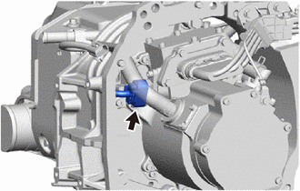
CHECK CONNECTOR CONNECTION CONDITION (DRIVE MOTOR RESOLVER CONNECTOR)
-
Check the connection condition of the drive motor resolver connector and the contact pressure of each terminal. Check the terminals for deformation, and check the connector for water ingress and foreign matter.
OK - The connector is connected securely. - The terminals are not deformed and are connected securely. - No water or foreign matter in the connector. Result Result Proceed to OK A NG (The connector is not connected securely.) B NG (The terminals are not making secure contact or are deformed, or water or foreign matter exists in the connector.) C
B
CONNECT SECURELY
C
REPAIR OR REPLACE HARNESS OR CONNECTOR
A
-
-
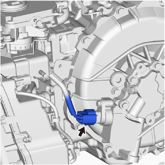
CHECK CONNECTOR CONNECTION CONDITION (FC AIR COMPRESSOR MOTOR RESOLVER CONNECTOR)
CAUTION:
Be sure to wear insulated gloves.
-
Check that the service plug grip is not installed to FC stack assembly and EV battery.
Note
After removing the service plug grip, do not turn the power switch on (READY), unless instructed by the repair manual because this may cause a malfunction.
-
Remove the FC air compressor with motor assembly.
-
Check the connection condition of the FC air compressor motor resolver connector and the contact pressure of each terminal. Check the terminals for deformation, and check the connector for water ingress and foreign matter.
OK - The connector is connected securely. - The terminals are not deformed and are connected securely. - No water or foreign matter in the connector. Result Result Proceed to OK A NG (The connector is not connected securely.) B NG (The terminals are not making secure contact or are deformed, or water or foreign matter exists in the connector.) C
A
REPLACE INVERTER WITH CONVERTER ASSEMBLY
B
CONNECT SECURELY
C
REPAIR OR REPLACE FC AIR COMPRESSOR REVOLUTION SENSOR WIRE
-
-
CHECK CONNECTOR CONNECTION CONDITION (DRIVE MOTOR RESOLVER CONNECTOR)
-
Check the connection condition of the drive motor resolver connector and the contact pressure of each terminal. Check the terminals for deformation, and check the connector for water ingress and foreign matter.
OK - The connector is connected securely. - The terminals are not deformed and are connected securely. - No water or foreign matter in the connector. Result Result Proceed to OK A NG (The connector is not connected securely.) B NG (The terminals are not making secure contact or are deformed, or water or foreign matter exists in the connector.) C
B
CONNECT SECURELY
C
REPAIR OR REPLACE HARNESS OR CONNECTOR
A
-
-
CHECK HARNESS AND CONNECTOR (INVERTER WITH CONVERTER ASSEMBLY - DRIVE MOTOR RESOLVER)
CAUTION:
Be sure to wear insulated gloves.
-
Check that the service plug grip is not installed to FC stack assembly and EV battery.
Note
After removing the service plug grip, do not turn the power switch on (READY), unless instructed by the repair manual because this may cause a malfunction.
-
Disconnect the inverter with converter assembly connector.
-
Disconnect the drive motor resolver connector.
-
Measure the resistance according to the value(s) in the table below.
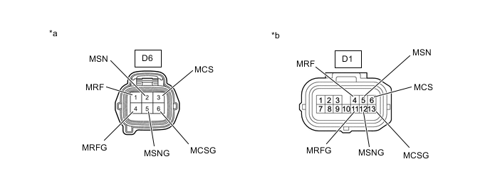
*a Front view of wire harness connector
(to Drive Motor Resolver)
*b Front view of wire harness connector
(to Inverter with Converter Assembly)
Standard Resistance Tester Connection Condition Specified Condition D1-4 (MRF) - D6-1 (MRF) Power switch off Below 1 Ω D1-11 (MRFG) - D6-4 (MRFG) Power switch off Below 1 Ω D1-5 (MSN) - D6-2 (MSN) Power switch off Below 1 Ω D1-12 (MSNG) - D6-5 (MSNG) Power switch off Below 1 Ω D1-6 (MCS) - D6-3 (MCS) Power switch off Below 1 Ω D1-13 (MCSG) - D6-6 (MCSG) Power switch off Below 1 Ω D1-4 (MRF) or D6-1 (MRF) - Body ground and other terminals Power switch off 1 MΩ or higher D1-11 (MRFG) or D6-4 (MRFG) - Body ground and other terminals Power switch off 1 MΩ or higher D1-5 (MSN) or D6-2 (MSN) - Body ground and other terminals Power switch off 1 MΩ or higher D1-12 (MSNG) or D6-5 (MSNG) - Body ground and other terminals Power switch off 1 MΩ or higher D1-6 (MCS) or D6-3 (MCS) - Body ground and other terminals Power switch off 1 MΩ or higher D1-13 (MCSG) or D6-6 (MCSG) - Body ground and other terminals Power switch off 1 MΩ or higher Tech Tips
The drive motor resolver is not available as a supply part. If it requires replacement, replace the FCV transaxle with motor assembly.
-
Reconnect the drive motor resolver connector.
-
Reconnect the inverter with converter assembly connector.
Result Proceed to OK NG
OK
REPLACE FCV TRANSAXLE WITH MOTOR ASSEMBLY
NG
REPAIR OR REPLACE HARNESS OR CONNECTOR
-
-
CHECK CONNECTOR CONNECTION CONDITION (FC AIR COMPRESSOR REVOLUTION SENSOR WIRE)
-
Check the connection condition of the FC air compressor revolution sensor wire connector and the contact pressure of each terminal. Check the terminals for deformation, and check the connector for water ingress and foreign matter.
OK - The connector is connected securely. - The terminals are not deformed and are connected securely. - No water or foreign matter in the connector. Result Result Proceed to OK A NG (The connector is not connected securely.) B NG (The terminals are not making secure contact or are deformed, or water or foreign matter exists in the connector.) C
B
CONNECT SECURELY
C
REPAIR OR REPLACE HARNESS OR CONNECTOR
A
-
-
CHECK HARNESS AND CONNECTOR (INVERTER WITH CONVERTER ASSEMBLY - FC AIR COMPRESSOR WITH MOTOR ASSEMBLY)
CAUTION:
Be sure to wear insulated gloves.
-
Check that the service plug grip is not installed to FC stack assembly and EV battery.
Note
After removing the service plug grip, do not turn the power switch on (READY), unless instructed by the repair manual because this may cause a malfunction.
-
Disconnect the inverter with converter assembly connector.
-
Disconnect the FC air compressor revolution sensor wire connector.
-
Measure the resistance according to the value(s) in the table below.
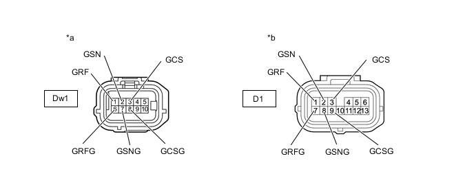
*a Front view of wire harness connector
(to FC Air Compressor Revolution Sensor Wire)
*b Front view of wire harness connector
(to Inverter with Converter Assembly)
Standard Resistance Tester Connection Condition Specified Condition D1-1 (GRF) - Dw1-1 (GRF) Power switch off Below 1 Ω D1-7 (GRFG) - Dw1-6 (GRFG) Power switch off Below 1 Ω D1-2 (GSN) - Dw1-2 (GSN) Power switch off Below 1 Ω D1-8 (GSNG) - Dw1-7 (GSNG) Power switch off Below 1 Ω D1-3 (GCS) - Dw1-3 (GCS) Power switch off Below 1 Ω D1-9 (GCSG) - Dw1-8 (GCSG) Power switch off Below 1 Ω D1-1 (GRF) or Dw1-1 (GRF) - Body ground and other terminals Power switch off 1 MΩ or higher D1-7 (GRFG) or Dw1-6 (GRFG) - Body ground and other terminals Power switch off 1 MΩ or higher D1-2 (GSN) or Dw1-2 (GSN) - Body ground and other terminals Power switch off 1 MΩ or higher D1-8 (GSNG) or Dw1-7 (GSNG) - Body ground and other terminals Power switch off 1 MΩ or higher D1-3 (GCS) or Dw1-3 (GCS) - Body ground and other terminals Power switch off 1 MΩ or higher D1-9 (GCSG) or Dw1-8 (GCSG) - Body ground and other terminals Power switch off 1 MΩ or higher -
Reconnect the FC air compressor revolution sensor wire connector.
-
Reconnect the inverter with converter assembly connector.
Result Proceed to OK NG
NG
REPAIR OR REPLACE HARNESS OR CONNECTOR
OK
-
-
CHECK CONNECTOR CONNECTION CONDITION (FC AIR COMPRESSOR MOTOR RESOLVER CONNECTOR)
CAUTION:
Be sure to wear insulated gloves.
-
Check that the service plug grip is not installed to FC stack assembly and EV battery.
Note
After removing the service plug grip, do not turn the power switch on (READY), unless instructed by the repair manual because this may cause a malfunction.
-
Remove the FC air compressor with motor assembly.
-
Check the connection condition of the FC air compressor motor resolver connector and the contact pressure of each terminal. Check the terminals for deformation, and check the connector for water ingress and foreign matter.
OK - The connector is connected securely. - The terminals are not deformed and are connected securely. - No water or foreign matter in the connector. Result Result Proceed to OK A NG (The connector is not connected securely.) B NG (The terminals are not making secure contact or are deformed, or water or foreign matter exists in the connector.) C
B
CONNECT SECURELY
C
REPAIR OR REPLACE FC AIR COMPRESSOR REVOLUTION SENSOR WIRE
A
-
-
CHECK FC AIR COMPRESSOR REVOLUTION SENSOR WIRE
CAUTION:
Be sure to wear insulated gloves.
-
Check that the service plug grip is not installed to FC stack assembly and EV battery.
Note
After removing the service plug grip, do not turn the power switch on (READY), unless instructed by the repair manual because this may cause a malfunction.
-
Remove the FC air compressor with motor assembly.
-
Remove the FC air compressor revolution sensor wire.
-
Measure the resistance according to the value(s) in the table below.
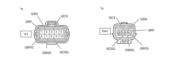
*a FC Air Compressor Revolution Sensor Wire
(FC Air Compressor Motor resolver Side)
*b FC Air Compressor Revolution Sensor Wire
(Inverter with Converter Assembly Side)
Standard Resistance Tester Connection Condition Specified Condition Dw1-1 (GRF) - w1-1 (GRF) Power switch off Below 1 Ω Dw1-6 (GRFG) - w1-6 (GRFG) Power switch off Below 1 Ω Dw1-2 (GSN) - w1-2 (GSN) Power switch off Below 1 Ω Dw1-7 (GSNG) - w1-7 (GSNG) Power switch off Below 1 Ω Dw1-3 (GCS) - w1-3 (GCS) Power switch off Below 1 Ω Dw1-8 (GCSG) - w1-8 (GCSG) Power switch off Below 1 Ω Dw1-1 (GRF) or w1-1 (GRF) - Body ground and other terminals Power switch off 1 MΩ or higher Dw1-6 (GRFG) or w1-6 (GRFG) - Body ground and other terminals Power switch off 1 MΩ or higher Dw1-2 (GSN) or w1-2 (GSN) - Body ground and other terminals Power switch off 1 MΩ or higher Dw1-7 (GSNG) or w1-7 (GSNG) - Body ground and other terminals Power switch off 1 MΩ or higher Dw1-3 (GCS) or w1-3 (GCS) - Body ground and other terminals Power switch off 1 MΩ or higher Dw1-8 (GCSG) or w1-8 (GCSG) - Body ground and other terminals Power switch off 1 MΩ or higher Tech Tips
The FC air compressor motor resolver is not available as a supply part. If it requires replacement, replace the FC air compressor with motor assembly.
-
Reconnect the FC air compressor revolution sensor wire.
-
Reinstall the FC air compressor with motor assembly.
Result Proceed to OK NG
OK
REPLACE FC AIR COMPRESSOR WITH MOTOR ASSEMBLY Click here
NG
REPAIR OR REPLACE FC AIR COMPRESSOR REVOLUTION SENSOR WIRE
-