HYBRID CONTROL SYSTEM, Diagnostic DTC:P0C30-390
| DTC Code | DTC Name |
|---|---|
| P0C30-390 | Battery Pack State of Charge High |
DESCRIPTION
The EV control ECU monitors its internal operation and will store a DTC and perform fail-safe control if it detects the following malfunction.
| DTC No. | Detection Item | DTC Detection Condition | Trouble Area | Warning Indicate |
|---|---|---|---|---|
| P0C30-390 | Battery Pack State of Charge High | Charge control malfunction: Charging of the EV battery continues even after charging is prohibited when the hybrid system is malfunctioning and "State of Charge (All Bat)" has reached the upper limit. (1 trip detection logic) |
EV control ECU | Master Warning Light: Comes on |
| DTC No. | Data List |
|---|---|
| P0C30-390 |
|
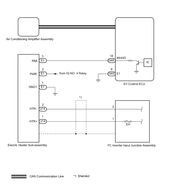
WIRING DIAGRAM
CAUTION / NOTICE / HINT
CAUTION:
-


Before the following operations are conducted, take precautions to prevent electric shock by turning the power switch off, wearing insulated gloves, and removing the service plug grips from both FC stack assembly and EV battery.
-
Inspecting the high-voltage system
-
Disconnecting the low voltage connector of the inverter with converter assembly
-
Disconnecting the low voltage connector of the EV battery
-
Disconnecting the low voltage connector of the FC stack assembly
-
Disconnecting the low voltage connector of the FC converter assembly
Tech Tips
No removal order is specified for the service plug grips of the FC stack assembly and EV battery.
-

After removing the service plug grip from the EV battery, put it in your pocket to prevent other technicians from accidentally reconnecting it while you are working on the high-voltage system. After removing the service grip from the FC stack assembly, store it in a safe location and use the "HIGH-VOLTAGE, DO NOT TOUCH" sign to notify other technicians that you are working on the high-voltage system.
-
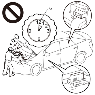
*a Without waiting for 10 minutes After removal of the service plug grips of both FC stack assembly and EV battery, wait for at least 10 minutes before touching the high-voltage connectors and terminals. After waiting for 10 minutes, check the voltage at the terminals in the inspection point in the inverter with converter assembly. The voltage should be 0 V before beginning work.
Tech Tips
At least 10 minutes are necessary to discharge the high-voltage capacitors inside the inverter with converter assembly and FC stack assembly.
Note
-
When the vehicle is parked with the power switch off, if the FC control ECU judges that the FC stack temperature will go below 0°C (32°F), it activates the FC air compressor, hydrogen pump and FC cooling water pump for a maximum of 180 seconds and drains water from the FC stack assembly. When performing inspection or repairs with the power switch off (not on (IG) or on (READY)), disconnect the cable from the negative (-) auxiliary battery terminal before performing work (If the auxiliary battery voltage is needed to conduct inspection, warm up the FC system beforehand).
-
Inspect the fuses for circuits related to this system before performing the following procedure.
-
After turning the power switch off, waiting time may be required before disconnecting the cable from the negative (-) auxiliary battery terminal. Therefore, make sure to read the disconnecting the cable from the negative (-) auxiliary battery terminal notices before proceeding with work.
-
The hybrid control system and air conditioning system output DTCs separately. Perform troubleshooting for the hybrid control system first if DTCs from these systems are output simultaneously.
-
The Vehicle Identification Number (VIN) or frame number must be input into a replacement EV control ECU.
Tech Tips
After the repair, clear the DTCs and perform the following procedure to check that DTCs are not output.
-
Connect the GTS to the DLC3.
-
Turn the power switch on (IG).
-
Enter the following menus: Powertrain / FC / Data List / FC Mode, FC Intermittent Operation.
-
Move the shift lever to P, turn the power switch on (READY) and wait until the FC system is started. Waiting for at least 2 minutes is required after turning the power switch on (READY).
-
FC system is started: "FC Working" is displayed for the Data List (FC) item "FC Mode" and "FC Intermittent Operation" is OFF.
-
With the power switch on (READY), and the vehicle stopped in the P position, depress the accelerator pedal. The FC system starts, and the Data List (EV) item "State of Charge (All Battery)" begins to increase.
If charge current drops, release the accelerator pedal and then depress it again to maintain charging.
-
Check that charging stops when "State of Charge (All Battery)" reaches the upper limit.
PROCEDURE
-
CHECK DTC OUTPUT (EV)
-
Connect the GTS to the DLC3.
-
Turn the power switch on (IG).
-
Enter the following menus: Powertrain / EV / Trouble Codes.
-
Check for DTCs.
Powertrain > EV > Trouble CodesResult Result Proceed to P0C30-390 only is output. A DTCs except P0C30-390 are output. B -
Turn the power switch off.
B 
GO TO DTC CHART (HYBRID CONTROL SYSTEM) Click here
A 
-
-
CHECK HARNESS AND CONNECTOR (ELECTRIC HEATER SUB-ASSEMBLY - POWER SOURCE CIRCUIT)
CAUTION:
-
Do not disconnect the connector on the high-voltage side.
-
Be sure to wear insulated gloves.
-
Check that the service plug grip is not installed to FC stack assembly and EV battery.
Note
After removing the service plug grip, do not turn the power switch on (READY), unless instructed by the repair manual because this may cause a malfunction.
-
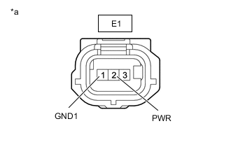
*a Front view of wire harness connector
(to Electric Heater Sub-assembly)
Disconnect the electric heater sub-assembly connector.
Note
Before disconnecting the connector, check that it is not loose or disconnected.
-
Measure the resistance according to the value(s) in the table below.
Standard Resistance Tester Connection Condition Specified Condition E1-1 (GND1) - Body ground Always Below 1 Ω Note
When taking a measurement with a tester, do not apply excessive force to the tester probe to avoid damaging the holder.
-
Reconnect the cable to the negative (-) auxiliary battery terminal.
-
Turn the power switch on (IG).
-
Measure the voltage according to the value(s) in the table below.
Standard Voltage Tester Connection Switch Condition Specified Condition E1-2 (PWR) - Body ground Power switch on (IG) 11 to 14 V E1-2 (PWR) - Body ground Power switch off Below 1 V Note
-
When taking a measurement with a tester, do not apply excessive force to the tester probe to avoid damaging the holder.
-
Turning the power switch on (IG) with the service plug grip removed causes DTCs to be stored. Clear the DTCs after performing this inspection.
-
Turning the power switch on (IG) with the electric heater sub-assembly connector disconnected causes other DTCs to be stored. Clear the DTCs after performing this inspection.
-
-
Turn the power switch off.
-
Disconnect the cable from the negative (-)auxiliary battery terminal.
-
Reconnect the electric heater sub-assembly connector.
Result Proceed to OK NG
NG
REPAIR OR REPLACE HARNESS OR CONNECTOR
OK
-
-
CHECK HARNESS AND CONNECTOR (ELECTRIC HEATER SUB-ASSEMBLY - EV CONTROL ECU)
-
Disconnect the E1 electric heater sub-assembly connector.
Note
Before disconnecting the connector, check that it is not loose or disconnected.
-
Disconnect the G46 EV control ECU connector.
Note
Before disconnecting the connector, check that it is not loose or disconnected.
-
Measure the resistance according to the value(s) in the table below.
Standard Resistance Tester Connection Condition Specified Condition E1-3 (RMI) - G46-18 (WHHD) Always Below 1 Ω E1-3 (RMI) or G46-18 (WHHD) - Body ground Always 10 kΩ or higher Note
When taking a measurement with a tester, do not apply excessive force to the tester probe to avoid damaging the holder.
-
Reconnect the E1 electric heater sub-assembly connector.
-
Reconnect the G46 EV control ECU connector.
Result Proceed to OK NG
NG
REPAIR OR REPLACE HARNESS OR CONNECTOR
OK
-
-
CHECK ELECTRIC HEATER SUB-ASSEMBLY OUTPUT
-
Disconnect the G46 EV control ECU connector.
Note
Before disconnecting the connector, check that it is not loose or disconnected.
-
Measure the voltage according to the value(s) in the table below.
Tester Connection Condition Specified Condition G46-18 (WHHD) - Body ground Power switch on (IG) Same as auxiliary battery voltage Note
When taking a measurement with a tester, do not apply excessive force to the tester probe to avoid damaging the holder.
-
Reconnect the G46 EV control ECU connector.
Result Proceed to OK NG
NG
REPLACE ELECTRIC HEATER SUB-ASSEMBLY Click here
OK
-
-
CHECK EV CONTROL ECU (WHHD TERMINAL)
-
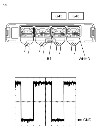
*a Component with harness connected
(EV Control ECU)
Remove the EV control ECU with the connectors still connected.
-
Measure the waveform of the EV control ECU connector.
OK Waveform is similar to that shown in the illustration. Item Content Tester Connection G46-18 (WHHD) - G45-6 (E1) Tool Setting 2 V/DIV., 5 ms/DIV. Vehicle Condition
-
Power switch on (Ready)
-
FC coolant temperature less than 50°C (122°F) EV system startup.
-
Blower speed: LO or more
-
Temperature setting: MAX HOT
Note
When taking a measurement with a tester, do not apply excessive force to the tester probe to avoid damaging the holder.
Tech Tips
The waveform varies with the duty ratio.
-
-
Reinstall the EV control ECU.
Result Proceed to OK NG
NG
REPLACE EV CONTROL ECU Click here
OK
-
-
INSPECT EH FUSE
CAUTION:
Be sure to wear insulated gloves.
-
Check that the service plug grip is not installed to FC stack assembly and EV battery.
Note
After removing the service plug grip, turning the power switch on (READY) may cause a malfunction. Do not turn the power switch on (READY) with the service plug grip removed.
-
Remove the junction block service cover.
Note
Be sure to prevent foreign matter or water from entering the FC inverter input junction assembly.
-
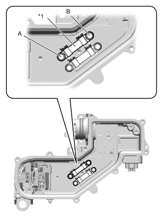
*1 EH Fuse Check that bolts A and B are tightened securely.
-
Measure the resistance according to the value(s) in the table below.
Standard Resistance Tester Item
(Tester Connection)
Condition Specified Condition EH fuse
(A - B)
Always Below 1 Ω -
Reinstall the junction block service cover.
Result Proceed to OK NG
NG
REPLACE EH FUSE AND ELECTRIC HEATER SUB-ASSEMBLY EH FUSE: Click here Electric heater sub-assembly: Click here Because the electric heater is the only possible cause of this fuse blowing, replace both the EH fuse and the electric heater sub-assembly at the same time.
OK
-
-
READ VALUE USING GTS (ENGINE COOLANT TEMP)
-
Connect the Techstream to the DLC3.
-
Turn the power switch on (IG).
-
Using the GTS, follow the instructions on the screen to perform the Active Test, and read the Data List values for the water temperature sensor.
-
Operate the integration control and panel assembly so that the following conditions are met.
Item Condition Temperature Setting MAX HOT Blower speed Lo ECO mode switch OFF Water Temperature Below 40°C -
Perform the Active Test according to the display on the GTS.
-
Set the heating three-way valve to the fully closed position.
Body Electrical > Air Conditioner > Active TestTester Display Measurement Item Control Range Diagnostic Note Heater Valve 3 way valve Close, Half, Open -
Body Electrical > Air Conditioner > Active TestTester Display Heater Valve -
-
Read the Data List according to the display on the GTS.
Body Electrical > Air Conditioner > Data ListTester Display Measurement Item Normal Condition Reference Value Diagnostic Note Engine Coolant Temp Heater core inlet water temperature Min.: 1.30°C(34.34°F)
Max.: 90.55°C(194.99°F)
Heater pipe (electric heater sub-assemblyto heater radiator unit sub-assembly) temperature displayed -
Body Electrical > Air Conditioner > Data ListTester Display Engine Coolant Temp
OK The value in the Data List rises Result Proceed to OK NG -
OK
HOW TO TROUBLESHOOT ECU CONTROLLED SYSTEMS Click here
NG
REPLACE ELECTRIC HEATER SUB-ASSEMBLY Click here
-