HYBRID CONTROL SYSTEM, Diagnostic DTC:P0AA6-485, P0AA6-486, P0AA6-487, P0AA6-488, P0AA6-526, P0AA6-611, P0AA6-612, P0AA6-613, P0AA6-614
| DTC Code | DTC Name |
|---|---|
| P0AA6-485 | EV Battery Voltage System Isolation Fault |
| P0AA6-486 | EV Battery Voltage System Isolation Fault |
| P0AA6-487 | EV Battery Voltage System Isolation Fault |
| P0AA6-488 | EV Battery Voltage System Isolation Fault |
| P0AA6-526 | EV Battery Voltage System Isolation Fault |
| P0AA6-611 | EV Battery Voltage System Isolation Fault |
| P0AA6-612 | EV Battery Voltage System Isolation Fault |
| P0AA6-613 | EV Battery Voltage System Isolation Fault |
| P0AA6-614 | EV Battery Voltage System Isolation Fault |
DESCRIPTION
The EV control ECU monitors the battery voltage sensor and detects insulation malfunctions in the high-voltage system.
For high voltage wiring diagrams, refer to the system description.
| DTC No. | Detection Item | DTC Detection Condition | Trouble Area | Warning Indicate |
|---|---|---|---|---|
| P0AA6-485 | EV Battery Voltage System Isolation Fault | Insulation resistance of the FC stack assembly, FC coolant or FC converter assembly has decreased.*2 (1 trip detection logic) |
|
Master Warning Light: Comes on |
| P0AA6-486 | EV Battery Voltage System Isolation Fault | Insulation resistance of the FC air compressor with motor assembly or inverter for the FC air compressor motor has decreased.*2 (1 trip detection logic) |
|
Master Warning Light: Comes on |
| P0AA6-487 | EV Battery Voltage System Isolation Fault | When the insulation resistance of the hydrogen pump, or the insulation resistance inside the FC water and hydrogen pump inverter assembly, has decreased.*2 (1 trip detection logic) |
|
Master Warning Light: Comes on |
| P0AA6-488 | EV Battery Voltage System Isolation Fault | When the insulation resistance of the FC cooling water pump assembly, or the insulation resistance inside the FC water and hydrogen pump inverter assembly, has decreased.*2 (1 trip detection logic) |
|
Master Warning Light: Comes on |
| P0AA6-526 | EV Battery Voltage System Isolation Fault | Insulation resistance between the high-voltage circuit and the body has decreased.*1 (1 trip detection logic) |
|
Master Warning Light: Comes on |
| P0AA6-611 | EV Battery Voltage System Isolation Fault | Insulation resistance of the compressor with motor assembly or air conditioning inverter has decreased.*2 (1 trip detection logic) |
Air conditioning system | Master Warning Light: Comes on |
| P0AA6-612 | EV Battery Voltage System Isolation Fault | Insulation resistance of the EV battery, battery voltage sensor or SMR has decreased.*2 (1 trip detection logic) |
|
Master Warning Light: Comes on |
| P0AA6-613 | EV Battery Voltage System Isolation Fault | Insulation resistance of the FCV transaxle with motor assembly or inverter for the drive motor has decreased.*2 (1 trip detection logic) |
|
Master Warning Light: Comes on |
| P0AA6-614 | EV Battery Voltage System Isolation Fault | Insulation resistance of the inverter for the FC air compressor motor and drive motor, A/C inverter, SMR, FC inverter input junction assembly, electric heater sub-assembly, FC water and hydrogen pump inverter assembly, FC converter power outlet cable, FC converter, No. 3 motor wire or frame wire has decreased.*2 (1 trip detection logic) |
|
Master Warning Light: Comes on |
Tech Tips
-
*1: The insulation malfunction detection circuit in the battery voltage sensor monitors the insulation resistance between the high voltage circuits and body. If the insulation resistance decreases, the EV control ECU stores DTC P0AA6-526 and illuminates the master warning light first regardless of malfunction area.
Sometimes the insulation malfunction is hard to duplicate due to the vehicle's condition changing. So if DTC P0AA6-526 outputs, complete the following steps as soon as possible.
-
*2: If the following operations are performed to determine the part with insufficient insulation resistance within the same trip after DTC P0AA6-526 only is stored, just one of the related DTCs (P0AA6-485, 486, 487, 488, 611, 612, 613 or 614) will likely be stored. If insulation malfunctions are occurring in several areas, the related DTCs will not be output but only DTC P0AA6-526 will be output.
- Operations to determine the part with insufficient insulation resistance
-
Wait for 5 minutes or more with the vehicle stopped, the power switch on (READY), the shift lever in P and the air conditioning system on (Lo/COOL MAX, blower speed HI).
-
After turning the power switch off (READY off), wait 5 minutes or more.
Tech Tips
DTCs and freeze frame data are useful information in determining the malfunctioning part. When the vehicle is brought to the workshop, read the DTCs and freeze frame data related to P0AA6 and make sure to record the information. (Even if the high-voltage insulation malfunction could not be reproduced, DTCs once memorized will not be cleared unless the clear operation is performed, so such DTCs can be read.)
-
When measuring insulation resistance using a megohmmeter, measure the resistance while jiggling the high voltage wire harness.
| DTC No. | Data List (EV) | Data List (FC) | Data List (FCDC) |
|---|---|---|---|
| P0AA6-485 |
|
|
|
| P0AA6-486 | |||
| P0AA6-487 | |||
| P0AA6-488 | |||
| P0AA6-526 | |||
| P0AA6-611 | |||
| P0AA6-612 | |||
| P0AA6-613 | |||
| P0AA6-614 |
Use the following items as a reference when duplicating the vehicle conditions at the time when the malfunction occurred.
-
Ready Signal
-
Vehicle Speed
-
Auxiliary Battery Voltage
-
State of Charge (All Battery)
Data List (EV)
-
FC Mode
-
FC Intermittent Operation
Data List (FC)
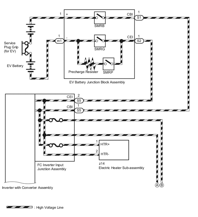
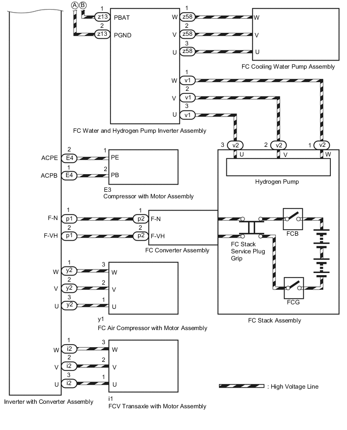
WIRING DIAGRAM
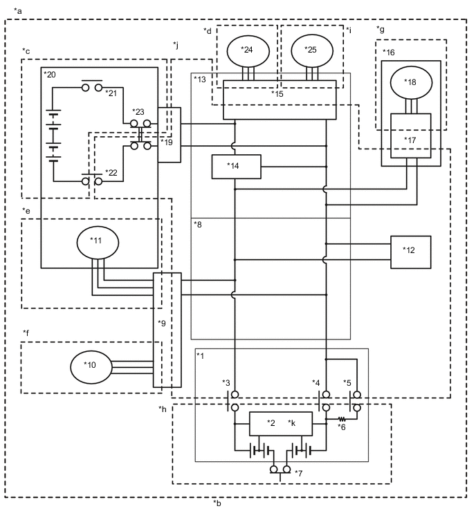
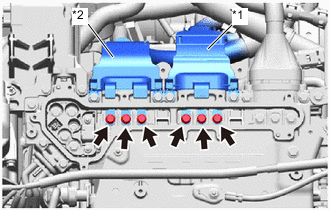
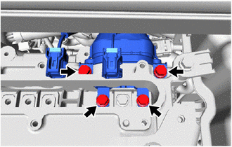
| *1 | EV Battery | *2 | Battery Voltage Sensor |
| *3 | SMRB | *4 | SMRG |
| *5 | SMRP | *6 | Precharge Resistor |
| *7 | Service Plug Grip (for EV) | *8 | FC Inverter Input Junction Assembly |
| *9 | FC Water and Hydrogen Pump Inverter Assembly | *10 | FC Cooling Water Pump Assembly |
| *11 | Hydrogen Pump | *12 | Electric Heater Sub-assembly |
| *13 | Inverter with Converter Assembly | *14 | Boost Converter |
| *15 | Inverter | *16 | Compressor with Motor Assembly |
| *17 | A/C Inverter | *18 | A/C Motor |
| *19 | FC Converter Assembly | *20 | FC Stack Assembly |
| *21 | FCB (FC relay (+)) | *22 | FCG (FC relay (-)) |
| *23 | FC Stack Service Plug Grip | *24 | FC Air Compressor with Motor Assembly |
| *25 | FCV Transaxle with Motor Assembly | - | - |
| *a | High-voltage Areas | *b | Information code 526 indicates that there is a decrease in the insulation resistance in any part of the high-voltage circuit. |
| *c |
FC Stack Areas |
*d |
FC Air Compressor Areas |
| *e |
Hydrogen Pump Areas |
*f |
FC Cooling Water Pump Areas |
| *g |
Air Conditioning System Areas |
*h |
EV Battery Areas |
| *i |
Transaxle Areas |
*j |
High-voltage Direct Current Areas |
| *k | Built-in abnormal insulation detection circuit | - | - |
SYSTEM DESCRIPTION
Tech Tips
If a decrease in insulation resistance cannot be confirmed using a megohmmeter, check "Short Wave Highest Val" in the Data List.
-
SHORT WAVE HIGHEST VALUE
-
"Short Wave Highest Val" indicates a decrease in insulation resistance and decreases the value as the insulation resistance decreases. In some cases, "Short Wave Highest Val" may decrease even though the insulation resistance of the vehicle is normal, therefore avoid checking "Short Wave Highest Val" when any of the following conditions exist.
-
From the time the power switch is turned on (READY) until approximately 10 minutes or more have elapsed.
-
There is change of the system voltages ("Power Resource VB", "VL-Voltage before Boosting", and "VH-Voltage after Boosting").
-
-
When "Short Wave Highest Val" is approximately 0 V, insulation resistance is close to 0 Ω. In this case, damage to a high-voltage cable or hybrid component (high-voltage), or a short to the body due to intrusion of foreign matter such as metal particles can be suspected.
-
-
-
If problem symptoms cannot be reproduced and a malfunction still exists after replacing a part as instructed, checking the following freeze frame data can help determine a trouble area.
Freeze Frame Data Diagnostic Note Short Wave Highest Voltage Indicates that the insulation resistance has decreased.
-
VL-Voltage before Boosting
-
VH-Voltage after Boosting
-
VB-Battery Voltage
-
Boost Ratio
During boosting (when "Boost Ratio" is not 0%), or when "VL-Voltage before Boosting", "VH-Voltage after Boosting" or "Power Resource VB" is varying, "Short Wave Highest Val" may decrease even though the insulation resistance is normal.
-
SMRP Status
-
SMRB Status
-
SMRG Status
When "SMRP Status", "SMRB Status" and "SMRG Status" are all OFF, the insulation malfunction detection circuit detects a decrease in insulation resistance in the EV battery area ((*h) in the wiring diagram).
-
When the power switch is turned on (IG) (not on (READY)), and all 3 system main relays are off, it is suspected that the EV battery assembly is disconnected from the high voltage circuits. If "Short Wave Highest Val" decreases a few minutes after the power switch is turned on (IG) (not on (READY)), the EV battery assembly may have an insulation malfunction.
Example:
Drive Motor Inverter Shutdown Request When "Drive Motor Inverter Shutdown Request" is ON, the insulation malfunction detection circuit cannot detect a decrease in insulation resistance in the drive motor system AC (alternating current) section (drive motor side of (*i) in the wiring diagram).
The drive motor system AC (alternating current) section includes the drive motor in the FCV transaxle with motor assembly, drive motor cables and the AC (alternating current) section of the motor drive circuit in the inverter with converter assembly.
FC Air Compressor Gate Shutdown Request When "FC Air Compressor Gate Shutdown Request" is ON, the insulation malfunction detection circuit cannot detect a decrease in insulation resistance in the FC air compressor motor system AC (alternating current) section (FC air compressor motor side of (*d) in the wiring diagram).
The FC air compressor system AC (alternating current) section includes the motor in the FC air compressor with motor assembly, FC air compressor motor cables and the AC (alternating current) section of the compressor motor drive circuit in the inverter with converter assembly.
A/C Consumption Power When the air conditioning system is off (air conditioning system power consumption is 0 W), the insulation malfunction detection circuit cannot detect a decrease in insulation resistance in the compressor with motor assembly AC (alternating current) section ((*g) in the wiring diagram).
The compressor with motor assembly AC (alternating current) section ((*g) in the wiring diagram) includes the air conditioning motor, wiring between the air conditioning motor and air conditioning inverter, and the AC (alternating current) section of the air conditioning motor drive circuit in the air conditioning inverter.
With the vehicle stopped, turn on/off the air conditioning system and observe "Short Wave Highest Val" to use as a diagnosis reference.
RELATED FREEZE FRAME DATA
Tech Tips
-
Reproducing the vehicle conditions the moment a DTC was stored according to the freeze frame data and results of the customer problem analysis helps ensure that the same DTC is stored again.
Driving Status Item Diagnostic Note Vehicle Speed - Accel Pedal Position No.1 - Shift Sensor Shift Position - Master Cylinder Control Torque - Operation Conditions Item Diagnostic Note Drive Motor Temperature If any liquid leaks into the ATF, insulation resistance may decrease only when the temperature is high.
The drive motor temperature is likely to increase if the drive motor speed is low and output torque is high such as when cruising uphill slowly or accelerating from a low speed.
-
Customer Problem Analysis
Ask the customer about the operating conditions and environment when the malfunction occurred.
Item Diagnostic Note Driving Condition (acceleration, deceleration, turning, etc.) Changes in the insulation of the parts with insufficient insulation due to changes in G force or vibration is suspected. Road Condition (unpaved, etc.) Weather (rain, snow, etc.) Water intrusion is suspected Washing the vehicle (Whether the malfunction occurred after washing the vehicle?)
-
-
FC COOLING SYSTEM CONFIRMATION ITEM
-
The FC cooling system may be the likely cause of DTCs P0AA6-526 and 485. If these DTCs are output, check the following items.
Item Diagnostic Note FC coolant refilling and replacement history Make sure that water, LLC or any coolant other than the specific coolant for the FC cooling system (Toyota genuine FC stack coolant) has never been added.
Tech Tips
Do not add or replace with water or any coolant other than the specific coolant, as the insulation resistance inside the FC stack assembly may decrease.
FC cooling water ion-exchanger element replacement history Make sure that the FC cooling water ion-exchanger element is not used beyond its design life.
Tech Tips
-
If it is used beyond its design life, the insulation resistance of the FC coolant will become insufficient, because the ion-exchange power decreases as the element is used over time.
-
When the life of the FC cooling water ion-exchanger element is near to the end, an alert message will be indicated on the multi-information display inside the combination meter to urge the user to replace it.
Whether the vehicle was left stationary for a long period of time Confirm the usage of the vehicle, and check whether the vehicle was left stationary for a long period of time.
Tech Tips
-
If the vehicle remains stationary for a long period, impurities in the FC coolant may increase, and these impurities will increase the electrical conductivity.
-
If insulation resistance is low immediately after the system is started, the electrical conductivity of the coolant may have increased because the vehicle had been left stationary for a long period of time. If this occurs, the system performs control to increase the amount of FC coolant flow to quickly restore the electrical conductivity to normal.
-
During the above control, the master warning light comes on and "FC System Check in Progress" is displayed on the multi-information display inside the combination meter. In addition, "FC System Check Completed" will be displayed on the multi-information display when the control completes.
-
-
-
CONFIRMATION AFTER REPLACING PARTS
After the repair, clear the DTCs and perform the following procedure to check that DTCs are not output. (Do not turn the power switch off (READY off) during this inspection.)
-
When the vehicle is stationary, turn the power switch on (READY) with the shift lever in P and wait for 10 minutes (*1) or more.
Note
*1: If "FC System Check in Progress" is displayed on the multi-information display inside the combination meter, wait until "FC System Check Completed" is displayed.
Waiting for at least 8 minutes is required until "FC System Check Complete" is displayed. The waiting time will be longer if the temperature of the FC coolant is high, such as immediately after the vehicle had been driven.
-
Turn the air conditioning system on (MAX COLD, blower speed HI).
-
Shift lever in P and wait for 5 minutes.
-
If the following operations are performed in the same trip after DTC P0AA6-526 is stored, the parts with insufficient resistance will be determined, and an additional DTC (P0AA6-485, 486, 487, 488, 611, 612, 613 or 614) will likely be stored.
- Operations to determine the part with insufficient insulation resistance
-
When the vehicle is stationary, turn the power switch on (READY) with the shift lever in P and the air conditioning system on (Lo/COOL MAX, blower speed HI), and wait for 5 minutes or more. Then turn the power switch off (READY not on) and wait for 5 minutes or more.
Tech Tips
If a DTC is not output, check the driving condition that the Data List item (Short Wave Highest Val) decreases.
-
If DTC P0AA6-526 is not output, proceed to the next step.
Note
Power is supplied to the drive motor only when the vehicle is driven. If a drop in insulation resistance is detected in the transaxle assembly area, perform the following procedure to drive the vehicle as DTC P0AA6-526 will not be output unless the vehicle is driven with the shift lever in D.
-
-
Drive the vehicle for approximately 5 minutes referring to the following freeze frame data items: "Vehicle Speed", "Shift Position", "Accel Pedal Position No.1", "Master Cylinder Control Torque", "Inverter Coolant Temperature", "FC Air Compressor Inverter Temperature", "Drive Motor Inverter Temperature".
(If the freeze frame data item "Vehicle Speed" is 10 km/h (6 mph) or less, drive the vehicle at 10 km/h (6 mph) or more.)
-
If the following operations are performed in the same trip after DTC P0AA6-526 is stored, the parts within sufficient insulation resistance will be determined, and a DTC (P0AA6-485, 486, 487, 488, 611, 612, 613 or 614) will be stored.
- Operations to determine the part with insufficient insulation resistance
-
When the vehicle is stationary, turn the power switch on (READY) with the shift lever in P and the air conditioning system on (Lo/COOL MAX, blower speed HI), and wait for 5 minutes or more. Then turn the power switch off (READY not on) and wait for 5 minutes or more.
Tech Tips
If a DTC is not output, check the driving condition that the Data List item (Short Wave Highest Val) decreases.
-
-
CAUTION / NOTICE / HINT
CAUTION:
-
When troubleshooting DTC P0AA6, use either a tool wrapped with vinyl insulation tape or an insulated tool (It is extremely dangerous when a high-voltage charge passes through a non-insulated tool causing a short).
-


Before the following operations are conducted, take precautions to prevent electric shock by turning the power switch off, wearing insulated gloves, and removing the service plug grips from both FC stack assembly and EV battery.
-
Inspecting the high-voltage system
-
Disconnecting the low voltage connector of the inverter with converter assembly
-
Disconnecting the low voltage connector of the EV battery
-
Disconnecting the low voltage connector of the FC stack assembly
-
Disconnecting the low voltage connector of the FC converter assembly
Tech Tips
No removal order is specified for the service plug grips of the FC stack assembly and EV battery.
-

After removing the service plug grip from the EV battery, put it in your pocket to prevent other technicians from accidentally reconnecting it while you are working on the high-voltage system. After removing the service grip from the FC stack assembly, store it in a safe location and use the "HIGH-VOLTAGE, DO NOT TOUCH" sign to notify other technicians that you are working on the high-voltage system.
-

*a Without waiting for 10 minutes After removal of the service plug grips of both FC stack assembly and EV battery, wait for at least 10 minutes before touching the high-voltage connectors and terminals. After waiting for 10 minutes, check the voltage at the terminals in the inspection point in the inverter with converter assembly. The voltage should be 0 V before beginning work.
Tech Tips
At least 10 minutes are necessary to discharge the high-voltage capacitors inside the inverter with converter assembly and FC stack assembly.
Note
-
After turning the power switch off, waiting time may be required before disconnecting the cable from the negative (-) auxiliary battery terminal. Therefore, make sure to read the disconnecting the cable from the negative (-) auxiliary battery terminal notices before proceeding with work.
-
When reinstalling the service plug grip to the FC stack assembly or the EV battery, slide the lever of the service plug until the letters "UNLOCK" are completely hidden, and insert it firmly.
-
When the vehicle is parked with the power switch off, if the FC control ECU judges that the FC stack temperature will go below 0°C (32°F), it activates the FC air compressor, hydrogen pump and FC cooling water pump for a maximum of 180 seconds and drains water from the FC stack assembly. When performing inspection or repairs with the power switch off (not on (IG) or on (READY)), disconnect the cable from the negative (-) auxiliary battery terminal before performing work (If the auxiliary battery voltage is needed to conduct inspection, warm up the FC system beforehand).
Tech Tips
When measuring insulation resistance using a megohmmeter, set the megohmmeter to 500 V.
PROCEDURE
-
CHECK DTC OUTPUT (EV)
-
Connect the GTS to the DLC3.
-
Turn the power switch on (IG).
-
Enter the following menus: Powertrain : Powertrain / EV / Trouble Codes.
-
Check for DTCs.
Powertrain > EV > Trouble CodesResult Result Proceed to P0AA6 only is output. A P0AA6 and P0A1D are output. B P0AA6 and P0AA7 are output. C P0AA6 and P0AFC are output. D -
Turn the power switch off.
B 
GO TO DTC CHART (P0A1D) Click here
C
GO TO DTC CHART (P0AA7) Click here
D
GO TO DTC CHART (P0AFC) Click here
A 
-
-
CHECK INFORMATION CODE
-
Connect the GTS to the DLC3.
-
Turn the power switch on (IG).
-
Enter the following menus: Powertrain : Powertrain / EV / Trouble Codes.
Powertrain > EV > Trouble Codes -
Access the freeze frame data of DTC P0AA6 and read the INF code.
Note
-
Information codes 485, 486, 487, 488, 611, 612, 613, and 614 are not stored at the same time INF code 526 is stored. If a drop in insulation resistance is detected and DTC P0AA6-526 is output, wait for 5 minutes with the power switch on (READY), the shift lever in P and the air conditioning system on (Lo/COOL MAX, blower speed HI), then turn the power switch off (READY not on) and wait for 5 minutes. An additional information code (485, 486, 487, 488, 611, 612, 613 or 614) indicating the part with insufficient resistance will likely be stored
-
When any other INF codes indicating parts which the insulation resistance dropped are output, perform the diagnostic procedure for each INF code.
Result Result Proceed to 526 (decrease in the insulation resistance of the high-voltage circuit) only is output. A 526 and 485 (decrease in the insulation resistance of the FC stack area) are output. B 526 and 486 (decrease in the insulation resistance of the FC air compressor area) are output. C 526 and 487 (decrease in the insulation resistance of the hydrogen pump area) are output. D 526 and 488 (decrease in the insulation resistance of the FC cooling water pump area) are output. E 526 and 611 (decrease in the insulation resistance of the air conditioning system area) are output. Refer to the troubleshooting procedure for P0AA6-611 (Air conditioning system)
526 and 612 (decrease in the insulation resistance of the EV battery area) are output. F 526 and 613 (decrease in the insulation resistance of the FCV transaxle with motor assembly area) are output. G 526 and 614 (decrease in the insulation resistance of the high-voltage direct current area) are output. H -
-
Turn the power switch off.
B 
CHECK FC STACK AREA (FC COOLING WATER ION EXCHANGER ELEMENT) Click here
C
CHECK FC AIR COMPRESSOR AREA (FC AIR COMPRESSOR WITH MOTOR ASSEMBLY) Click here
D
CHECK HYDROGEN PUMP AREA (FC WATER AND HYDROGEN PUMP INVERTER ASSEMBLY (HYDROGEN PUMP SIDE)) Click here
E
CHECK FC COOLING WATER PUMP AREA (FC COOLING WATER PUMP ASSEMBLY) Click here
F
CHECK EV BATTERY AREA Click here
G
CHECK TRANSAXLE AREA (FCV TRANSAXLE WITH MOTOR ASSEMBLY) Click here
H
HIGH VOLTAGE DIRECT CURRENT AREA Click here
A
-
-
RECONFIRM DTC OUTPUT
-
Turn the power switch off and wait for 3 minutes or more.
-
Connect the GTS to the DLC3.
-
Wait for 1 minute or more with the power switch on (READY), the shift lever in P, and the air conditioning system on (Lo/COOL MAX, blower speed HI).(*1)
-
Turn the power switch off and wait for 5 minutes or more.(*2)
-
Turn the power switch on (IG).
-
Enter the following menus: Powertrain : Powertrain / EV / Trouble Codes.
Powertrain > EV > Trouble Codes -
Access the freeze frame data of DTC P0AA6 and read the INF code.
Note
-
Information codes 485, 486, 487, 488, 611, 612, 613 and 614 are not stored at the same time INF code 526 is stored. If a drop in insulation resistance is detected and DTC P0AA6-526 is output, proceed with the above mentioned steps (*1) to (*3). An additional information code (485, 486, 487, 488, 611, 612, 613 or 614) indicating the part with insufficient resistance will likely be stored.
-
If only DTC P0AA6-526 is output, perform the diagnostic procedure for INF code 526 to inspect all the high voltage circuits.
-
When any other INF codes indicating parts which the insulation resistance dropped are output, perform the diagnostic procedure for each INF code.
Result Result Proceed to 526 (decrease in the insulation resistance of the high-voltage circuit) only is output. A 485 (decrease in the insulation resistance of the FC stack area) are output. B 486 (decrease in the insulation resistance of the FC air compressor area) are output. C 487 (decrease in the insulation resistance of the hydrogen pump area) are output. D 488 (decrease in the insulation resistance of the FC cooling water pump area) are output. E 526 and 611 (decrease in the insulation resistance of the air conditioning system area) are output. Refer to the troubleshooting procedure for P0AA6-611 (Air conditioning system)
526 and 612 (decrease in the insulation resistance of the EV battery area) are output. F 526 and 613 (decrease in the insulation resistance of the FCV transaxle with motor assembly area) are output. G 526 and 614 (decrease in the insulation resistance of the high-voltage direct current area) are output. H -
-
Turn the power switch off.
B
GO TO STEP 35 Click here
C
GO TO STEP 46 Click here
D
GO TO STEP 48 Click here
E
GO TO STEP 53 Click here
F
GO TO STEP 56 Click here
G
GO TO STEP 61 Click here
H
GO TO STEP 63 Click here
A
-
-
CHECK FC COOLING WATER ION EXCHANGER ELEMENT
-
Make sure that the FC cooling water ion-exchanger element is not used beyond its design life.
Tech Tips
-
If it is used beyond its design life, the insulation resistance of the FC coolant will become insufficient, because the ion-exchange power decreases as the element is used over time.
-
When the life of the FC cooling water ion-exchanger element is near to the end, an alert message "Ion Filter Maintenance Required Visit Your Dealer" will be indicated on the multi-information display inside the combination meter.
Result Result Proceed to "Ion Filter Maintenance Required Visit Your Dealer" is not displayed in the multi-information display of the combination meter. A "Ion Filter Maintenance Required Visit Your Dealer" is displayed in the multi-information display of the combination meter. B -
B
REPLACE FC COOLING WATER ION EXCHANGER ELEMENT Click here
A
-
-
READ VALUE USING GTS (SHORT WAVE HIGHEST VOLTAGE)
-
Connect the GTS to the DLC3.
-
Turn the power switch on (IG).
-
Enter the following menus: Powertrain / EV / Short Wave Highest Voltage
Powertrain > EV > Data ListTester Display Short Wave Highest Voltage -
After turning the power switch on (IG), wait 1 minute or more and check "Short Wave Highest Voltage".
Note
Avoid checking "Short Wave Highest Voltage" within 1 minute after the power switch is turned on (IG). The value becomes different when it is read immediately after the power switch is turned on (IG).
OK "Short Wave Highest Voltage" is 3.1 V or more with the power switch on (IG). Tech Tips
If "Short Wave Highest Voltage" decreases with the power switch on (IG) (the SMR not connected), it is determined that insulation resistance has decreased in the EV battery area.
Result Proceed to OK NG
NG
GO TO STEP 56 Click here
OK
-
-
CHECK FCV TRANSAXLE WITH MOTOR ASSEMBLY (DRIVE MOTOR CABLE)
CAUTION:
Be sure to wear insulated gloves.
-
Check that the service plug grip is not installed to FC stack assembly and EV battery.
Note
After removing the service plug grip, do not turn the power switch on (READY), unless instructed by the repair manual because this may cause a malfunction.
-
Remove the inverter terminal cover from the inverter with converter assembly.
Tech Tips
Make sure that no foreign matter, coolant or water has entered the inverter assembly with converter. Confirm that the inverter coolant volume has not increased.
-
*1 FC Air Compressor Motor Cable *2 Drive Motor Cable Disconnect the FC air compressor motor cable and drive motor cable from the inverter with converter assembly.
-
Connect the cable to the negative (-) auxiliary battery terminal.
Tech Tips
As the insulation resistance may vary when drive motor rotates, perform this inspection while rotating the front wheels.
-
Turn the power switch on (IG).
Note
Turning the power switch on (IG) with the service plug grip removed causes DTCs to be stored. Clear the DTCs after performing this inspection.
-
Move the shift lever to N and lift the vehicle.
-
Turn the power switch off and wait for 3 minutes or more.
-
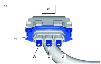
*1 Shield Ground *a Drive Motor Cable
(Inverter with Converter Assembly Side)
Using a megohmmeter set to 500 V, measure the resistance according to the value(s) in the table below while rotating the front wheels 2 revolutions in the same direction simultaneously.
Note
-
Carefully perform this inspection as the drive motor may generate current when the front wheels are rotated by hand.
-
Be sure to set the megohmmeter to 500 V when performing this test. Using a setting higher than 500 V can result in damage to the component being inspected.
Standard Resistance Tester Connection Condition Specified Condition i2-3 (U) - Body ground and shielded wire ground Power switch off 100 MΩ or higher i2-2 (V) - Body ground and shielded wire ground Power switch off 100 MΩ or higher i2-1 (W) - Body ground and shielded wire ground Power switch off 100 MΩ or higher -
-
Lower the vehicle and move the shift lever to P.
-
Disconnect the cable from the negative (-) auxiliary battery terminal.
Result Proceed to OK NG
NG
GO TO STEP 62 Click here
OK
-
-
CHECK FC AIR COMPRESSOR WITH MOTOR ASSEMBLY
CAUTION:
Be sure to wear insulated gloves.
-
Check that the service plug grip is not installed to FC stack assembly and EV battery.
Note
After removing the service plug grip, do not turn the power switch on (READY), unless instructed by the repair manual because this may cause a malfunction.
-
Connect the cable to the negative (-) auxiliary battery terminal.
-
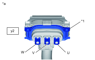
*1 Shield Ground *a FC Air Compressor Motor Cable
(Inverter with Converter Assembly Side)
Measure the resistance according to the value(s) in the table below.
Note
Be sure to set the megohmmeter to 500 V when performing this test. Using a setting higher than 500 V can result in damage to the component being inspected.
Standard Resistance Tester Connection Condition Specified Condition y2-3 (U) - Body ground and shielded wire ground Power switch off 10 MΩ or higher y2-2 (V) - Body ground and shielded wire ground Power switch off 10 MΩ or higher y2-1 (W) - Body ground and shielded wire ground Power switch off 10 MΩ or higher -
Disconnect the cable from the negative (-) auxiliary battery terminal.
Result Proceed to OK NG
NG
GO TO STEP 47 Click here
OK
-
-
CHECK FC CONVERTER ASSEMBLY
CAUTION:
Be sure to wear insulated gloves.
-
Check that the service plug grip is not installed to FC stack assembly and EV battery.
Note
After removing the service plug grip, do not turn the power switch on (READY), unless instructed by the repair manual because this may cause a malfunction.
-
Disconnect the FC converter power outlet cable from the inverter with converter assembly.
-
*1 Shield Ground *a FC Converter Power Outlet Cable
(Inverter with Converter Assembly Side)
Using a megohmmeter set to 500 V, measure the resistance according to the value(s) in the table below.
CAUTION:
-
Do not disconnect any other connectors from the FC converter assembly when performing the inspection because this may cause damage to the FC converter assembly.
-
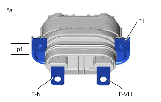
This inspection is performed to check the insulation resistance between the high voltage terminals and body ground. Never check resistance between the high voltage wire harnesses (F-VH - F-N) using the megohmmeter.
Standard Resistance Tester Connection Condition Specified Condition p1-1 (F-N) - Body ground and shielded wire ground Power switch off 2 MΩ or higher *1 p1-2 (F-VH) - Body ground and shielded wire ground Power switch off 2 MΩ or higher *1 Note
-
*1: Read the resistance value immediately after connecting the megohmmeter as the value will change during the measurement.
-
Be sure to set the megohmmeter to 500 V when performing this test. Using a setting higher than 500 V can result in damage to the component being inspected.
Result Proceed to OK NG -
NG
GO TO STEP 75 Click here
OK
-
-
CHECK FC STACK ASSEMBLY
CAUTION:
Be sure to wear insulated gloves.
-
Check that the service plug grip is not installed to FC stack assembly and EV battery.
Note
After removing the service plug grip, do not turn the power switch on (READY), unless instructed by the repair manual because this may cause a malfunction.
-
Disconnect the FC converter power outlet cable from the inverter with converter assembly.
-
Install the FC stack service plug grip.
-
*1 Shield Ground *a FC Converter Power Outlet Cable
(Inverter with Converter Assembly Side)
Using a megohmmeter set to 500 V, measure the resistance according to the value(s) in the table below.
CAUTION:
-
Do not disconnect any other connectors from the FC converter assembly when performing the inspection because this may cause damage to the FC converter assembly.
-
This inspection is performed to check the insulation resistance between the high voltage terminals and body ground. Never check resistance between the high voltage wire harnesses (F-VH - F-N) using the megohmmeter.
Standard Resistance Tester Connection Condition Specified Condition p1-1 (F-N) - Body ground and shielded wire ground Power switch off 2 MΩ or higher *1 p1-2 (F-VH) - Body ground and shielded wire ground Power switch off 2 MΩ or higher *1 Note
-
*1: Read the resistance value immediately after connecting the megohmmeter as the value will change during the measurement.
-
Be sure to set the megohmmeter to 500 V when performing this test. Using a setting higher than 500 V can result in damage to the component being inspected.
-
-
Remove the FC stack service plug grip.
Result Proceed to OK NG
NG
REPLACE FC STACK ASSEMBLY Click here
OK
-
-
CHECK NO. 3 MOTOR WIRE
CAUTION:
Be sure to wear insulated gloves.
-
Check that the service plug grip is not installed to FC stack assembly and EV battery.
Note
After removing the service plug grip, do not turn the power switch on (READY), unless instructed by the repair manual because this may cause a malfunction.
-
Disconnect the No. 3 motor wire from the inverter with converter assembly.
Tech Tips
Make sure that no foreign matter has entered or contaminated the No. 3 motor wire (air conditioning harness).
-
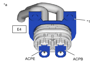
*1 Shield Ground *a No. 3 motor wire (Air Conditioner Harness)
(Inverter with Converter Assembly Side)
Using a megohmmeter set to 500 V, measure the resistance according to the value(s) in the table below.
Note
Be sure to set the megohmmeter to 500 V when performing this test. Using a setting higher than 500 V can result in damage to the component being inspected.
Standard Resistance Tester Connection Condition Specified Condition E4-1 (ACPE) - Body ground and shielded wire ground Power switch off 3 MΩ or higher E4-2 (ACPB) - Body ground and shielded wire ground Power switch off 3 MΩ or higher Result Proceed to OK NG
NG
GO TO STEP 80 Click here
OK
-
-
CHECK FC WATER AND HYDROGEN PUMP INVERTER ASSEMBLY
CAUTION:
Be sure to wear insulated gloves.
-
Check that the service plug grip is not installed to FC stack assembly and EV battery.
Note
After removing the service plug grip, do not turn the power switch on (READY), unless instructed by the repair manual because this may cause a malfunction.
-
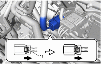
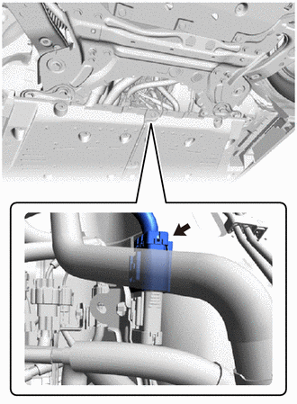
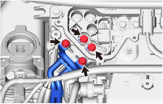
*1 Green Lock Disconnect the FC inverter input junction assembly connector from the FC water and hydrogen pump inverter assembly.
Tech Tips
Make sure that no foreign matter has entered or contaminated the FC inverter input junction assembly connector.
-
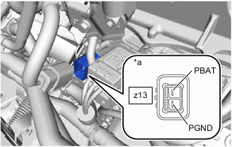
*a Component without harness connected
(FC Water and Hydrogen Pump Inverter Assembly)
Using a megohmmeter set to 500 V, measure the resistance according to the value(s) in the table below.
Note
Be sure to set the megohmmeter to 500 V when performing this test. Using a setting higher than 500 V can result in damage to the component being inspected.
Standard Resistance Tester Connection Condition Specified Condition z13-1 (PBAT) - Body ground Power switch off 10 MΩ or higher z13-2 (PGND) - Body ground Power switch off 10 MΩ or higher Result Proceed to OK NG
NG
REPLACE FC WATER AND HYDROGEN PUMP INVERTER ASSEMBLY Click here
OK
-
-
CHECK FC COOLING WATER PUMP ASSEMBLY
CAUTION:
Be sure to wear insulated gloves.
-
Check that the service plug grip is not installed to FC stack assembly and EV battery.
Note
After removing the service plug grip, do not turn the power switch on (READY), unless instructed by the repair manual because this may cause a malfunction.
-
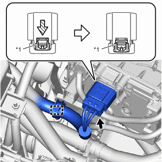
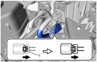
*1 Green Lock Disconnect the FC cooling water pump assembly connector from the FC water and hydrogen pump inverter assembly.
-
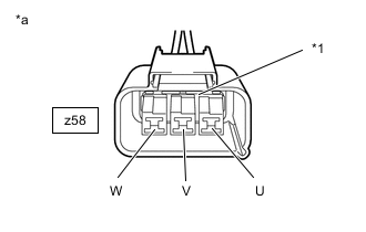
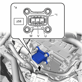
*1 Shield Ground *a FC Cooling Water Pump Assembly
(FC Water and Hydrogen Pump Inverter Assembly Side)
Using a megohmmeter set to 500 V, measure the resistance according to the value(s) in the table below.
Note
Be sure to set the megohmmeter to 500 V when performing this test. Using a setting higher than 500 V can result in damage to the component being inspected.
Standard Resistance Tester Connection Condition Specified Condition z58-1 (W) - Body ground and shielded wire ground Power switch off 10 MΩ or higher z58-2 (V) - Body ground and shielded wire ground Power switch off 10 MΩ or higher z58-3 (U) - Body ground and shielded wire ground Power switch off 10 MΩ or higher Result Proceed to OK NG
NG
REPLACE FC COOLING WATER PUMP ASSEMBLY Click here
OK
-
-
CHECK FC WATER AND HYDROGEN PUMP INVERTER ASSEMBLY (FC WATER PUMP)
CAUTION:
Be sure to wear insulated gloves.
-
Check that the service plug grip is not installed to FC stack assembly and EV battery.
Note
After removing the service plug grip, do not turn the power switch on (READY), unless instructed by the repair manual because this may cause a malfunction.
-
*1 Shield Ground *a Component without harness connected
(FC Water and Hydrogen Pump Inverter Assembly)
Measure the resistance according to the value(s) in the table below.
Note
Be sure to set the megohmmeter to 500 V when performing this test. Using a setting higher than 500 V can result in damage to the component being inspected.
Standard Resistance Tester Connection Condition Specified Condition z58-3 (U) - Body ground and shielded wire ground Power switch off 10 MΩ or higher z58-2 (V) - Body ground and shielded wire ground Power switch off 10 MΩ or higher z58-1 (W) - Body ground and shielded wire ground Power switch off 10 MΩ or higher Result Proceed to OK NG
NG
REPLACE FC WATER AND HYDROGEN PUMP INVERTER ASSEMBLY Click here
OK
-
-
CHECK FC WATER AND HYDROGEN PUMP INVERTER ASSEMBLY (HYDROGEN PUMP SIDE)
CAUTION:
Be sure to wear insulated gloves.
-
Check that the service plug grip is not installed to FC stack assembly and EV battery.
Note
After removing the service plug grip, do not turn the power switch on (READY), unless instructed by the repair manual because this may cause a malfunction.
-
Disconnect the hydrogen pump inverter cable connector.
-
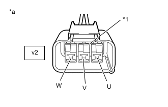
*1 Shield Ground *a Hydrogen Pump Inverter Cable
(FC Stack Assembly Side)
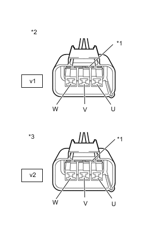
Using a megohmmeter set to 500 V, measure the resistance according to the value(s) in the table below.
Note
Be sure to set the megohmmeter to 500 V when performing this test. Using a setting higher than 500 V can result in damage to the component being inspected.
Standard Resistance Tester Connection Condition Specified Condition v2-1 (W) - Body ground and shielded wire ground Power switch off 10 MΩ or higher v2-2 (V) - Body ground and shielded wire ground Power switch off 10 MΩ or higher v2-3 (U) - Body ground and shielded wire ground Power switch off 10 MΩ or higher Result Proceed to OK NG
NG
GO TO STEP 50 Click here
OK
-
-
INSPECT FC STACK ASSEMBLY (HYDROGEN PUMP)
CAUTION:
Be sure to wear insulated gloves.
-
Check that the service plug grip is not installed to FC stack assembly and EV battery.
Note
After removing the service plug grip, do not turn the power switch on (READY), unless instructed by the repair manual because this may cause a malfunction.
-
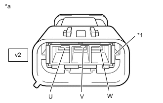
*1 Shield Ground *a FC Stack Assembly (Hydrogen Pump)
(Hydrogen Pump Inverter Cable Side)
Using a megohmmeter set to 500 V, measure the resistance according to the value(s) in the table below.
Note
Be sure to set the megohmmeter to 500 V when performing this test. Using a setting higher than 500 V can result in damage to the component being inspected.
Standard Resistance Tester Connection Condition Specified Condition v2-1 (W) - Body ground and shielded wire ground Power switch off 50 MΩ or higher v2-2 (V) - Body ground and shielded wire ground Power switch off 50 MΩ or higher v2-3 (U) - Body ground and shielded wire ground Power switch off 50 MΩ or higher Result Proceed to OK NG
NG
REPLACE FC STACK ASSEMBLY (HYDROGEN PUMP) Click here
OK
-
-
CHECK ELECTRIC HEATER SUB-ASSEMBLY
CAUTION:
Be sure to wear insulated gloves.
-
Check that the service plug grip is not installed to FC stack assembly and EV battery.
Note
After removing the service plug grip, do not turn the power switch on (READY), unless instructed by the repair manual because this may cause a malfunction.
-
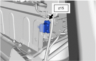
*1 Green Lock Disconnect the electric heater sub-assembly connector.
-
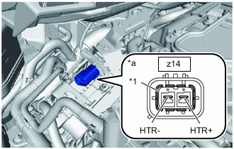
*1 Shield Ground *a Component without harness connected
(Electric Heater Sub-assembly)
Using a megohmmeter set to 500 V, measure the resistance according to the value(s) in the table below.
Note
Be sure to set the megohmmeter to 500 V when performing this test. Using a setting higher than 500 V can result in damage to the component being inspected.
Standard Resistance Tester Connection Condition Specified Condition z14-1 (HTR+) - Body ground and shielded wire ground Power switch off 10 MΩ or higher z14-2 (HTR-) - Body ground and shielded wire ground Power switch off 10 MΩ or higher Result Proceed to OK NG
NG
REPLACE ELECTRIC HEATER SUB-ASSEMBLY Click here
OK
-
-
CHECK INVERTER WITH CONVERTER ASSEMBLY
CAUTION:
Be sure to wear insulated gloves.
-
Check that the service plug grip is not installed to FC stack assembly and EV battery.
Note
After removing the service plug grip, do not turn the power switch on (READY), unless instructed by the repair manual because this may cause a malfunction.
-
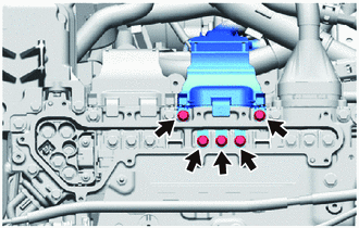
Disconnect the FC inverter input junction cover from the FC inverter input junction assembly.
-
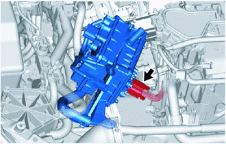
Disconnect the frame wire from the FC inverter input junction assembly.
Tech Tips
Make sure that no foreign matter has entered or contaminated the frame wire.
-
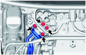
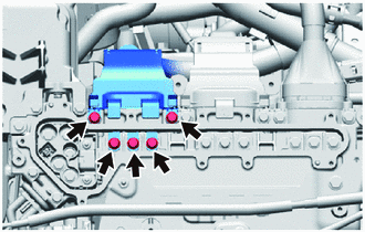
*1 High voltage terminal Using a megohmmeter set to 500 V, measure the resistance according to the value(s) in the table below.
Note
Be sure to set the megohmmeter to 500 V when performing this test. Using a setting higher than 500 V can result in damage to the component being inspected.
Standard Resistance Tester Connection Condition Specified Condition High voltage terminal - Body ground Power switch off 1 MΩ or higher Tech Tips
Perform this inspection with the drive motor cable, FC air compressor motor cable, FC converter power outlet cable and No. 3 motor wire (air conditioning harness) disconnected from the inverter with converter assembly.
Result Proceed to OK NG
NG
CHECK FC INVERTER INPUT JUNCTION ASSEMBLY Click here
OK
-
-
CHECK FRAME WIRE
CAUTION:
Be sure to wear insulated gloves.
-
Check that the service plug grip is not installed to FC stack assembly and EV battery.
Note
After removing the service plug grip, do not turn the power switch on (READY), unless instructed by the repair manual because this may cause a malfunction.
-
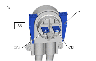
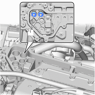
*1 Shield Ground *a Frame Wire
(FC Inverter Input Junction Assembly Side)
Using a megohmmeter set to 500 V, measure the resistance according to the value(s) in the table below.
Note
Be sure to set the megohmmeter to 500 V when performing this test. Using a setting higher than 500 V can result in damage to the component being inspected.
Standard Resistance Tester Connection Condition Specified Condition S5-1 (CBI) - Body ground and shielded wire ground Power switch off 10 MΩ or higher S5-2 (CEI) - Body ground and shielded wire ground Power switch off 10 MΩ or higher Tech Tips
Visually inspect the frame wire for damage. If there is any damage, then this is the likely cause of low insulation resistance.
Result Proceed to OK NG
NG
GO TO STEP 83 Click here
OK
-
-
CHECK FC COOLANT
-
Check FC coolant (Toyota genuine FC stack coolant) replacement history.
Tech Tips
Do not add or mix water or any coolant other than the specific coolant (Toyota genuine FC stack coolant), as the insulation resistance inside the FC stack assembly may decrease and cause DTC P0AA6 to be stored.
Note
If filling of water or any coolant other than the specific coolant is confirmed, replace the coolant following the procedure in the "Countermeasures when coolant (Toyota genuine FC stack coolant) passages are filled incorrectly" section.
Result Result Proceed to Coolant or water other than FC coolant (Toyota genuine FC stack coolant ) is not filled. A Coolant or water other than FC coolant (Toyota genuine FC stack coolant ) is filled. B
B
REPLACE COOLANT (FC STACK COOLANT) Click here
A
-
-
ASK ABOUT VEHICLE CONDITION (VEHICLE IS LEFT UNUSED FOR A LONG PERIOD OF TIME)
-
Confirm the usage of the vehicle, and check whether the vehicle was left stationary for a long period of time.
Tech Tips
-
If the vehicle remains stationary for a long period, impurities in the FC coolant may increase, and these impurities will increase the electrical conductivity.
-
If insulation resistance is low immediately after the system is started, the electrical conductivity of the coolant may have increased because the vehicle had been left stationary for a long period of time. If this occurs, the system performs control to increase the amount of FC coolant flow to quickly restore the electrical conductivity to normal.
-
During the above control, the master warning light comes on, "FC System Check in Progress" is displayed on the multi-information display inside the combination meter, and the warning buzzer sounds. In addition, "FC System Check Completed" will be displayed on the multi-information display when the control completes.
Result Result Proceed to The vehicle was left stationary for a long period of time. A The vehicle was not left stationary for a long period of time. B -
B
PERFORM CONFIRMATION AFTER REPLACING PARTS Click here
A
-
-
PERFORM CONFIRMATION AFTER REPLACING PARTS
-
Clear the DTC.
-
Disconnect the cable from the negative (-) auxiliary battery terminal wait for 90 seconds or more.
-
Connect the cable to the negative (-) auxiliary battery terminal.
-
Turn the power switch on (READY) with the shift lever in P and wait for 2 minutes or more.
-
If "FC System Check in Progress" is displayed on the multi-information display inside the combination meter, wait until "FC System Check Completed" is displayed.
Tech Tips
-
Waiting for at least 8 minutes is required until "FC System Check Complete" is displayed. The waiting time will be longer if the temperature of the FC coolant is high, such as immediately after the vehicle had been driven.
-
If the power switch is turned on (READY) but "FC System Check in Progress" will not be displayed on the multi-information display inside the combination meter, proceed to B.
-
-
Perform confirmation after replacing repairs.
Result Result Proceed to P0AA6 is output again. A P0AA6 is not output. B
A
GO TO STEP 25 Click here
B
COMPLETED
-
-
PERFORM CONFIRMATION AFTER REPLACING PARTS
-
Perform confirmation after completing repairs.
Result Result Proceed to P0AA6 is output again. A P0AA6 is not output. B
B
COMPLETED
A
-
-
REPLACE FC STACK ASSEMBLY
Result Proceed to NEXT
NEXT
-
REPLACE FC CONVERTER ASSEMBLY
Result Proceed to NEXT
NEXT
PERFORM CONFIRMATION AFTER REPLACING PARTS Click here
-
REPLACE COOLANT (FC STACK COOLANT)
-
Note
Replace the coolant and the FC cooling water ion-exchanger element following the procedure in the "Countermeasures when coolant (Toyota genuine FC stack coolant) passages are filled incorrectly" section.
Result Proceed to NEXT
NEXT
PERFORM CONFIRMATION AFTER REPLACING PARTS Click here
-
-
CHECK FC INVERTER INPUT JUNCTION ASSEMBLY
CAUTION:
Be sure to wear insulated gloves.
-
Check that the service plug grip is not installed to FC stack assembly and EV battery.
Note
After removing the service plug grip, do not turn the power switch on (READY), unless instructed by the repair manual because this may cause a malfunction.
-

Disconnect the FC inverter input junction assembly from the inverter with converter assembly.
-
*1 High voltage terminal Using a megohmmeter set to 500 V, measure the resistance according to the value(s) in the table below.
Note
Be sure to set the megohmmeter to 500 V when performing this test. Using a setting higher than 500 V can result in damage to the component being inspected.
Standard Resistance Tester Connection Condition Specified Condition High voltage terminal - Body ground Power switch off 1 MΩ or higher Tech Tips
Perform this inspection with the drive motor cable, FC air compressor motor cable, FC inverter input junction assembly, FC converter power outlet cable and No. 3 motor wire (air conditioning harness) disconnected from the inverter with converter assembly.
Result Proceed to OK NG
NG
GO TO STEP 73 Click here
OK
-
-
REPLACE FC INVERTER INPUT JUNCTION ASSEMBLY
Result Proceed to NEXT
NEXT
PERFORM CONFIRMATION AFTER REPLACING PARTS Click here
-
REPLACE ELECTRIC HEATER SUB-ASSEMBLY
Result Proceed to NEXT
NEXT
PERFORM CONFIRMATION AFTER REPLACING PARTS Click here
-
REPLACE FC STACK ASSEMBLY (HYDROGEN PUMP)
Result Proceed to NEXT
NEXT
PERFORM CONFIRMATION AFTER REPLACING PARTS Click here
-
REPLACE FC WATER AND HYDROGEN PUMP INVERTER ASSEMBLY
Result Proceed to NEXT
NEXT
PERFORM CONFIRMATION AFTER REPLACING PARTS Click here
-
REPLACE FC COOLING WATER PUMP ASSEMBLY
Result Proceed to NEXT
NEXT
PERFORM CONFIRMATION AFTER REPLACING PARTS Click here
-
REPLACE FC WATER AND HYDROGEN PUMP INVERTER ASSEMBLY
Result Proceed to NEXT
NEXT
PERFORM CONFIRMATION AFTER REPLACING PARTS Click here
-
REPLACE FC STACK ASSEMBLY
Result Proceed to NEXT
NEXT
PERFORM CONFIRMATION AFTER REPLACING PARTS Click here
-
REPLACE FC COOLING WATER ION EXCHANGER ELEMENT
Result Proceed to NEXT
NEXT
PERFORM CONFIRMATION AFTER REPLACING PARTS Click here
-
CHECK FC STACK AREA (FC COOLING WATER ION EXCHANGER ELEMENT)
-
Make sure that the FC cooling water ion-exchanger element is not used beyond its design life.
Tech Tips
-
If it is used beyond its design life, the insulation resistance of the FC coolant will become insufficient, because the ion-exchange power decreases as the element is used over time.
-
When the life of the FC cooling water ion-exchanger element is near to the end, an alert message "Ion Filter Maintenance Required Visit Your Dealer" will be indicated on the multi-information display inside the combination meter.
Result Result Proceed to "Ion Filter Maintenance Required Visit Your Dealer" is not displayed in the multi-information display of the combination meter. A "Ion Filter Maintenance Required Visit Your Dealer" is displayed in the multi-information display of the combination meter. B -
B
REPLACE FC COOLING WATER ION EXCHANGER ELEMENT Click here
A
-
-
CHECK FC COOLANT
-
Check FC coolant (Toyota genuine FC stack coolant) replacement history.
Tech Tips
Do not add or mix water or any coolant other than the specific coolant (Toyota genuine FC stack coolant), as the insulation resistance inside the FC stack assembly may decrease and cause DTC P0AA6 to be stored.
Note
If filling of water or any coolant other than the specific coolant is confirmed, replace the coolant following the procedure in the "Countermeasures when coolant (Toyota genuine FC stack coolant) passages are filled incorrectly" section.
Result Result Proceed to Coolant or water other than FC coolant (Toyota genuine FC stack coolant ) is not filled. A Coolant or water other than FC coolant (Toyota genuine FC stack coolant ) is filled. B
B
REPLACE COOLANT (FC STACK COOLANT) Click here
A
-
-
ASK ABOUT VEHICLE CONDITION (VEHICLE IS LEFT UNUSED FOR A LONG PERIOD OF TIME)
-
Confirm the usage of the vehicle, and check whether the vehicle was left stationary for a long period of time.
Tech Tips
-
If the vehicle remains stationary for a long period, impurities in the FC coolant may increase, and these impurities will increase the electrical conductivity.
-
If insulation resistance is low immediately after the system is started, the electrical conductivity of the coolant may have increased because the vehicle had been left stationary for a long period of time. If this occurs, the system performs control to increase the amount of FC coolant flow to quickly restore the electrical conductivity to normal.
-
During the above control, the master warning light comes on, "FC System Check in Progress" is displayed on the multi-information display inside the combination meter, and the warning buzzer sounds. In addition, "FC System Check Completed" will be displayed on the multi-information display when the control completes.
Result Result Proceed to The vehicle was left stationary for a long period of time. A The vehicle was not left stationary for a long period of time. B -
B
PERFORM CONFIRMATION AFTER REPLACING PARTS Click here
A
-
-
PERFORM CONFIRMATION AFTER REPLACING PARTS
-
Clear the DTCs and freeze frame data.
-
Disconnect the cable from the negative (-) auxiliary battery terminal wait for 90 seconds or more.
-
Connect the cable to the negative (-) auxiliary battery terminal.
-
Turn the power switch on (READY) with the shift lever in P and wait for 2 minutes or more.
-
If "FC System Check in Progress" is displayed on the multi-information display inside the combination meter, wait until "FC System Check Completed" is displayed.
Tech Tips
-
Waiting for at least 8 minutes is required until "FC System Check Complete" is displayed. The waiting time will be longer if the temperature of the FC coolant is high, such as immediately after the vehicle had been driven.
-
If the power switch is turned on (READY) but "FC System Check in Progress" will not be displayed on the multi-information display inside the combination meter, proceed to B.
-
-
Perform confirmation after completing repairs.
Result Result Proceed to P0AA6 is output again. A P0AA6 is not output. B
B
COMPLETED
A
-
-
REPLACE COOLANT (FC STACK COOLANT)
-
Replace the FC coolant (Toyota genuine FC stack coolant) and the FC cooling water ion-exchanger element.
Note
Replace the coolant and the FC cooling water ion-exchanger element following the procedure in the "Countermeasures when coolant (Toyota genuine FC stack coolant) passages are filled incorrectly" section.
Result Proceed to NEXT
NEXT
-
-
PERFORM CONFIRMATION AFTER REPLACING PARTS
-
Perform confirmation after completing repairs.
Result Result Proceed to P0AA6 is output again. A P0AA6 is not output. B
B
COMPLETED
A
-
-
CHECK FC CONVERTER ASSEMBLY
CAUTION:
Be sure to wear insulated gloves.
-
Check that the service plug grip is not installed to FC stack assembly and EV battery.
Note
After removing the service plug grip, do not turn the power switch on (READY), unless instructed by the repair manual because this may cause a malfunction.
-
Disconnect the FC converter power outlet cable from the inverter with converter assembly.
-
*1 Shield Ground *a Converter Power Outlet Cable
(Inverter with Converter Assembly Side)
Using a megohmmeter set to 500 V, measure the resistance according to the value(s) in the table below.
CAUTION:
-
Do not disconnect any other connectors from the FC converter assembly when performing the inspection because this may cause damage to the FC converter assembly.
-
This inspection is performed to check the insulation resistance between the high voltage terminals and body ground. Never check resistance between the high voltage wire harnesses (F-VH - F-N) using the megohmmeter.
Standard Resistance Tester Connection Condition Specified Condition p1-1 (F-N) - Body ground and shielded wire ground Power switch off 2 MΩ or higher *1 p1-2 (F-VH) - Body ground and shielded wire ground Power switch off 2 MΩ or higher *1 Note
-
*1: Read the resistance value immediately after connecting the megohmmeter as the value will change during the measurement.
-
Be sure to set the megohmmeter to 500 V when performing this test. Using a setting higher than 500 V can result in damage to the component being inspected.
Result Proceed to OK NG -
NG
REPLACE FC CONVERTER ASSEMBLY Click here
OK
-
-
REPLACE FC STACK ASSEMBLY
Result Proceed to NEXT
NEXT
PERFORM CONFIRMATION AFTER REPLACING PARTS Click here
-
REPLACE FC CONVERTER ASSEMBLY
Result Proceed to NEXT
NEXT
PERFORM CONFIRMATION AFTER REPLACING PARTS Click here
-
REPLACE COOLANT (FC STACK COOLANT)
-
Replace the FC coolant (Toyota genuine FC stack coolant) and the FC cooling water ion-exchanger element.
Note
Replace the coolant and the FC cooling water ion-exchanger element following the procedure in the "Countermeasures when coolant (Toyota genuine FC stack coolant) passages are filled incorrectly" section
Result Proceed to NEXT
NEXT
PERFORM CONFIRMATION AFTER REPLACING PARTS Click here
-
-
REPLACE FC COOLING WATER ION EXCHANGER ELEMENT
Result Proceed to NEXT
NEXT
PERFORM CONFIRMATION AFTER REPLACING PARTS Click here
-
CHECK FC AIR COMPRESSOR AREA (FC AIR COMPRESSOR WITH MOTOR ASSEMBLY)
CAUTION:
Be sure to wear insulated gloves.
-
Check that the service plug grip is not installed to FC stack assembly and EV battery.
Note
After removing the service plug grip, do not turn the power switch on (READY), unless instructed by the repair manual because this may cause a malfunction.
-
Remove the inverter terminal cover from the inverter with converter assembly.
Tech Tips
Make sure that no foreign matter, coolant or water has entered the inverter assembly with converter. Confirm that the inverter coolant volume has not increased.
-
Disconnect the FC air compressor cable from the inverter with converter assembly.
-
*1 Shield Ground *a FC Air Compressor Motor Cable
(Inverter with Converter Assembly Side)
Measure the resistance according to the value(s) in the table below.
Note
Be sure to set the megohmmeter to 500 V when performing this test. Using a setting higher than 500 V can result in damage to the component being inspected.
Standard Resistance Tester Connection Condition Specified Condition y2-3 (U) - Body ground and shielded wire ground Power switch off 10 MΩ or higher y2-2 (V) - Body ground and shielded wire ground Power switch off 10 MΩ or higher y2-1 (W) - Body ground and shielded wire ground Power switch off 10 MΩ or higher Result Proceed to OK NG
OK
GO TO STEP 73 Click here
NG
-
-
REPLACE FC AIR COMPRESSOR WITH MOTOR ASSEMBLY
Result Proceed to NEXT
NEXT
PERFORM CONFIRMATION AFTER REPLACING PARTS Click here
-
CHECK HYDROGEN PUMP AREA (FC WATER AND HYDROGEN PUMP INVERTER ASSEMBLY (HYDROGEN PUMP SIDE))
CAUTION:
Be sure to wear insulated gloves.
-
Check that the service plug grip is not installed to FC stack assembly and EV battery.
Note
After removing the service plug grip, do not turn the power switch on (READY), unless instructed by the repair manual because this may cause a malfunction.
-
Disconnect the hydrogen pump inverter cable from the FC stack assembly.
-
*1 Shield Ground *a Hydrogen Pump Inverter Cable
(FC Stack Assembly Side)
Using a megohmmeter set to 500 V, measure the resistance according to the value(s) in the table below.
Note
Be sure to set the megohmmeter to 500 V when performing this test. Using a setting higher than 500 V can result in damage to the component being inspected.
Standard Resistance Tester Connection Condition Specified Condition v2-1 (W) - Body ground and shielded wire ground Power switch off 10 MΩ or higher v2-2 (V) - Body ground and shielded wire ground Power switch off 10 MΩ or higher v2-3 (U) - Body ground and shielded wire ground Power switch off 10 MΩ or higher Result Proceed to OK NG
NG
CHECK HYDROGEN PUMP INVERTER CABLE Click here
OK
-
-
REPLACE FC STACK ASSEMBLY (HYDROGEN PUMP)
Result Proceed to NEXT
NEXT
PERFORM CONFIRMATION AFTER REPLACING PARTS Click here
-
CHECK HYDROGEN PUMP INVERTER CABLE
CAUTION:
Be sure to wear insulated gloves.
-
Check that the service plug grip is not installed to FC stack assembly and EV battery.
Note
After removing the service plug grip, do not turn the power switch on (READY), unless instructed by the repair manual because this may cause a malfunction.
-
Disconnect the hydrogen pump inverter cable from the FC water and hydrogen pump inverter assembly.
-
Disconnect the hydrogen pump inverter cable from the FC stack assembly.
-
*1 Shield Ground *a Hydrogen Pump Inverter Cable
(FC Water and Hydrogen Pump Inverter Assembly Side)
*b Hydrogen Pump Inverter Cable
(FC Stack Assembly Side)
Using a megohmmeter set to 500 V, measure the resistance according to the value(s) in the table below.
Note
Be sure to set the megohmmeter to 500 V when performing this test. Using a setting higher than 500 V can result in damage to the component being inspected.
Standard Resistance Tester Connection Condition Specified Condition v1-1 (W) - Body ground and shielded wire ground Power switch off 10 MΩ or higher v1-2 (V) - Body ground and shielded wire ground Power switch off 10 MΩ or higher v1-3 (U) - Body ground and shielded wire ground Power switch off 10 MΩ or higher v2-1 (W) - Body ground and shielded wire ground Power switch off 10 MΩ or higher v2-2 (V) - Body ground and shielded wire ground Power switch off 10 MΩ or higher v2-3 (U) - Body ground and shielded wire ground Power switch off 10 MΩ or higher Note
Wrap each terminal of the hydrogen pump inverter cable with protective tape to prevent them from touching the body ground.
-
Measure the resistance according to the value(s) in the table below.
Standard Resistance Tester Connection Condition Specified Condition v1-1 (W) - v2-1 (W) IG OFF Below 1 Ω v1-2 (V) - v2-2 (V) IG OFF Below 1 Ω v1-3 (U) - v2-3 (U) IG OFF Below 1 Ω v1-1 (W) - v2-3 (U) IG OFF 100 MΩ or higher v1-2 (V) - v2-1 (W) IG OFF 100 MΩ or higher v1-3 (U) - v2-2 (V) IG OFF 100 MΩ or higher Result Proceed to OK NG
NG
REPLACE HYDROGEN PUMP INVERTER CABLE Click here
OK
-
-
REPLACE FC WATER AND HYDROGEN PUMP INVERTER ASSEMBLY
Result Proceed to NEXT
NEXT
PERFORM CONFIRMATION AFTER REPLACING PARTS Click here
-
REPLACE HYDROGEN PUMP INVERTER CABLE
Result Proceed to NEXT
NEXT
PERFORM CONFIRMATION AFTER REPLACING PARTS Click here
-
CHECK FC COOLING WATER PUMP AREA (FC COOLING WATER PUMP ASSEMBLY)
CAUTION:
Be sure to wear insulated gloves.
-
Check that the service plug grip is not installed to FC stack assembly and EV battery.
Note
After removing the service plug grip, do not turn the power switch on (READY), unless instructed by the repair manual because this may cause a malfunction.
-
*1 Green Lock Disconnect the FC cooling water pump assembly from the FC water and hydrogen pump inverter assembly.
-
*1 Shield Ground *a FC Cooling Water Pump Assembly
(FC Water and Hydrogen Pump Inverter Assembly Side)
Using a megohmmeter set to 500 V, measure the resistance according to the value(s) in the table below.
Note
Be sure to set the megohmmeter to 500 V when performing this test. Using a setting higher than 500 V can result in damage to the component being inspected.
Standard Resistance Tester Connection Condition Specified Condition z58-1 (W) - Body ground and shielded wire ground Power switch off 10 MΩ or higher z58-2 (V) - Body ground and shielded wire ground Power switch off 10 MΩ or higher z58-3 (U) - Body ground and shielded wire ground Power switch off 10 MΩ or higher Result Proceed to OK NG
NG
REPLACE FC COOLING WATER PUMP ASSEMBLY Click here
OK
-
-
REPLACE FC WATER AND HYDROGEN PUMP INVERTER ASSEMBLY
Result Proceed to NEXT
NEXT
PERFORM CONFIRMATION AFTER REPLACING PARTS Click here
-
REPLACE FC COOLING WATER PUMP ASSEMBLY
Result Proceed to NEXT
NEXT
PERFORM CONFIRMATION AFTER REPLACING PARTS Click here
-
CHECK EV BATTERY AREA
CAUTION:
Be sure to wear insulated gloves.
Tech Tips
Make sure that no foreign matter or water has entered the EV battery.
-
Check that the service plug grip is not installed to FC stack assembly and EV battery.
Note
After removing the service plug grip, do not turn the power switch on (READY), unless instructed by the repair manual because this may cause a malfunction.
-
Remove the No. 2 EV battery shield panel.
-
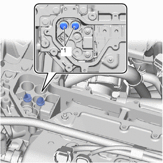
Disconnect the battery voltage sensor connector.
-
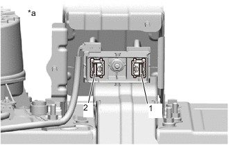
*a Component without service plug grip (for EV) installed
(EV Battery)
Using a megohmmeter set to 500 V, measure the resistance according to the value(s) in the table below.
Note
Be sure to set the megohmmeter to 500 V when performing this test. Using a setting higher than 500 V can result in damage to the component being inspected.
Standard Resistance Tester Connection Condition Specified Condition 1 - Body ground Power switch off 10 MΩ or higher 2 - Body ground Power switch off 10 MΩ or higher Result Proceed to OK NG
NG
CHECK EV BATTERY Click here
OK
-
-
REPLACE BATTERY VOLTAGE SENSOR
Result Proceed to NEXT
NEXT
PERFORM CONFIRMATION AFTER REPLACING PARTS Click here
-
CHECK EV BATTERY
CAUTION:
Be sure to wear insulated gloves.
-
Check that the service plug grip is not installed to FC stack assembly and EV battery.
Note
After removing the service plug grip, do not turn the power switch on (READY), unless instructed by the repair manual because this may cause a malfunction.
-
Remove the EV battery junction block assembly.
-
*a Component without service plug grip (for EV) installed
(EV battery)
Using a megohmmeter set to 500 V, measure the resistance according to the value(s) in the table below.
Note
Be sure to set the megohmmeter to 500 V when performing this test. Using a setting higher than 500 V can result in damage to the component being inspected.
Standard Resistance Tester Connection Condition Specified Condition 1 - Body ground Power switch off 10 MΩ or higher 2 - Body ground Power switch off 10 MΩ or higher Result Proceed to OK NG
NG
REPLACE EV BATTERY Click here
OK
-
-
REPLACE EV BATTERY JUNCTION BLOCK ASSEMBLY
Result Proceed to NEXT
NEXT
PERFORM CONFIRMATION AFTER REPLACING PARTS Click here
-
REPLACE EV BATTERY
Result Proceed to NEXT
NEXT
PERFORM CONFIRMATION AFTER REPLACING PARTS Click here
-
CHECK TRANSAXLE AREA (FCV TRANSAXLE WITH MOTOR ASSEMBLY)
CAUTION:
Be sure to wear insulated gloves.
-
Check that the service plug grip is not installed to FC stack assembly and EV battery.
Note
After removing the service plug grip, do not turn the power switch on (READY), unless instructed by the repair manual because this may cause a malfunction.
-
Remove the inverter terminal cover from the inverter with converter assembly.
Tech Tips
Make sure that no foreign matter, coolant or water has entered the inverter assembly with converter. Confirm that the inverter coolant volume has not increased.
-
Disconnect the drive motor cable from the inverter with converter assembly.
-
*1 Shield Ground *a Drive Motor Cable
(Inverter with Converter Assembly Side)
Using a megohmmeter set to 500 V, measure the resistance according to the value(s) in the table below while rotating the front wheels 2 revolutions in the same direction simultaneously.
Note
-
Carefully perform this inspection as the drive motor may generate current when the front wheels are rotated by hand.
-
Be sure to set the megohmmeter to 500 V when performing this test. Using a setting higher than 500 V can result in damage to the component being inspected.
Standard Resistance Tester Connection Condition Specified Condition i2-3 (U) - Body ground and shielded wire ground Power switch off 100 MΩ or higher i2-2 (V) - Body ground and shielded wire ground Power switch off 100 MΩ or higher i2-1 (W) - Body ground and shielded wire ground Power switch off 100 MΩ or higher Result Proceed to OK NG -
OK
GO TO STEP 73 Click here
NG
-
-
REPLACE FCV TRANSAXLE WITH MOTOR ASSEMBLY
Result Proceed to NEXT
NEXT
PERFORM CONFIRMATION AFTER REPLACING PARTS Click here
-
HIGH VOLTAGE DIRECT CURRENT AREA
CAUTION:
Be sure to wear insulated gloves.
-
Check that the service plug grip is not installed to FC stack assembly and EV battery.
Note
After removing the service plug grip, do not turn the power switch on (READY), unless instructed by the repair manual because this may cause a malfunction.
-
Remove the inverter terminal cover from the inverter with converter assembly.
Tech Tips
Make sure that no foreign matter, coolant or water has entered the inverter assembly with converter. Confirm that the inverter coolant volume has not increased.
-
Disconnect the FC inverter input junction cover from the FC inverter input junction assembly.
-
Disconnect the frame wire from the FC inverter input junction assembly.
Tech Tips
Make sure that no foreign matter has entered or contaminated the frame wire.
-
*1 Shield Ground *a Frame Wire
(FC Inverter Input Junction Assembly Side)
Using a megohmmeter set to 500 V, measure the resistance according to the value(s) in the table below.
Note
Be sure to set the megohmmeter to 500 V when performing this test. Using a setting higher than 500 V can result in damage to the component being inspected.
Standard Resistance Tester Connection Condition Specified Condition S5-1 (CBI) - Body ground and shielded wire ground Power switch off 10 MΩ or higher S5-2 (CEI) - Body ground and shielded wire ground Power switch off 10 MΩ or higher Tech Tips
Visually inspect the frame wire for damage. If there is any damage, then this is the likely cause of low insulation resistance.
Result Proceed to OK NG
NG
CHECK FRAME WIRE Click here
OK
-
-
CHECK NO. 3 MOTOR WIRE
CAUTION:
Be sure to wear insulated gloves.
-
Check that the service plug grip is not installed to FC stack assembly and EV battery.
Note
After removing the service plug grip, do not turn the power switch on (READY), unless instructed by the repair manual because this may cause a malfunction.
-
Disconnect the No. 3 motor wire from the inverter with converter assembly.
Tech Tips
Make sure that no foreign matter has entered or contaminated the No. 3 motor wire (air conditioning harness).
-
*1 Shield Ground *a No. 3 Motor Wire
(Inverter with Converter Assembly Side)
Using a megohmmeter set to 500 V, measure the resistance according to the value(s) in the table below.
Note
Be sure to set the megohmmeter to 500 V when performing this test. Using a setting higher than 500 V can result in damage to the component being inspected.
Standard Resistance Tester Connection Condition Specified Condition E4-1 (ACPE) - Body ground and shielded wire ground Power switch off 3 MΩ or higher E4-2 (ACPB) - Body ground and shielded wire ground Power switch off 3 MΩ or higher Result Proceed to OK NG
NG
CHECK NO. 3 MOTOR WIRE Click here
OK
-
-
CHECK FC WATER AND HYDROGEN PUMP INVERTER ASSEMBLY
CAUTION:
Be sure to wear insulated gloves.
-
Check that the service plug grip is not installed to FC stack assembly and EV battery.
Note
After removing the service plug grip, do not turn the power switch on (READY), unless instructed by the repair manual because this may cause a malfunction.
-
*1 Green Lock Disconnect the FC inverter input junction assembly connector from the FC water and hydrogen pump inverter assembly.
Tech Tips
Make sure that no foreign matter has entered or contaminated the FC inverter input junction assembly connector.
-
*a Component without harness connected
(FC Water and Hydrogen Pump Inverter Assembly)
Using a megohmmeter set to 500 V, measure the resistance according to the value(s) in the table below.
Note
Be sure to set the megohmmeter to 500 V when performing this test. Using a setting higher than 500 V can result in damage to the component being inspected.
Standard Resistance Tester Connection Condition Specified Condition z13-1 (PBAT) - Body ground Power switch off 10 MΩ or higher z13-2 (PGND) - Body ground Power switch off 10 MΩ or higher Result Proceed to OK NG
NG
REPLACE FC WATER AND HYDROGEN PUMP INVERTER ASSEMBLY Click here
OK
-
-
CHECK ELECTRIC HEATER SUB-ASSEMBLY
CAUTION:
Be sure to wear insulated gloves.
-
Check that the service plug grip is not installed to FC stack assembly and EV battery.
Note
After removing the service plug grip, do not turn the power switch on (READY), unless instructed by the repair manual because this may cause a malfunction.
-
*1 Green Lock Disconnect the electric heater sub-assembly connector.
-
*1 Shield Ground *a Component without harness connected
(Electric Heater Sub-assembly)
Using a megohmmeter set to 500 V, measure the resistance according to the value(s) in the table below.
Note
Be sure to set the megohmmeter to 500 V when performing this test. Using a setting higher than 500 V can result in damage to the component being inspected.
Standard Resistance Tester Connection Condition Specified Condition z14-1 (HTR+) - Body ground and shielded wire ground Power switch off 10 MΩ or higher z14-2 (HTR-) - Body ground and shielded wire ground Power switch off 10 MΩ or higher Result Proceed to OK NG
NG
REPLACE ELECTRIC HEATER SUB-ASSEMBLY Click here
OK
-
-
CHECK FC CONVERTER ASSEMBLY
CAUTION:
Be sure to wear insulated gloves.
-
Check that the service plug grip is not installed to FC stack assembly and EV battery.
Note
After removing the service plug grip, do not turn the power switch on (READY), unless instructed by the repair manual because this may cause a malfunction.
-
Disconnect the FC converter power outlet cable from the inverter with converter assembly.
-
*1 Shield Ground *a Converter Power Outlet Cable
(Inverter with Converter Assembly Side)
Using a megohmmeter set to 500 V, measure the resistance according to the value(s) in the table below.
CAUTION:
-
Do not disconnect any other connectors from the FC converter assembly when performing the inspection because this may cause damage to the FC converter assembly.
-
This inspection is performed to check the insulation resistance between the high voltage terminals and body ground. Never check resistance between the high voltage wire harnesses (F-VH - F-N) using the megohmmeter.
Standard Resistance Tester Connection Condition Specified Condition p1-1 (F-N) - Body ground and shielded wire ground Power switch off 2 MΩ or higher *1 p1-2 (F-VH) - Body ground and shielded wire ground Power switch off 2 MΩ or higher *1 Note
-
*1: Read the resistance value immediately after connecting the megohmmeter as the value will change during the measurement.
-
Be sure to set the megohmmeter to 500 V when performing this test. Using a setting higher than 500 V can result in damage to the component being inspected.
Result Proceed to OK NG -
NG
CHECK FC CONVERTER POWER OUTLET CABLE Click here
OK
-
-
CHECK FC STACK ASSEMBLY
CAUTION:
Be sure to wear insulated gloves.
-
Check that the service plug grip is not installed to FC stack assembly and EV battery.
Note
After removing the service plug grip, do not turn the power switch on (READY), unless instructed by the repair manual because this may cause a malfunction.
-
Disconnect the FC converter power outlet cable from the inverter with converter assembly.
-
Install the FC stack service plug grip.
-
*1 Shield Ground *a FC Converter Power Outlet Cable
(Inverter with Converter Assembly Side)
Using a megohmmeter set to 500 V, measure the resistance according to the value(s) in the table below.
CAUTION:
-
This inspection is performed to check the insulation resistance between the high voltage terminals and body ground. Never check resistance between the high voltage wire harnesses (F-VH - F-N) using the megohmmeter.
-
Do not disconnect any other connectors from the FC converter assembly when performing the inspection because this may cause damage to the FC converter assembly.
Standard Resistance Tester Connection Condition Specified Condition p1-1 (F-N) - Body ground and shielded wire ground Power switch off 2 MΩ or higher *1 p1-2 (F-VH) - Body ground and shielded wire ground Power switch off 2 MΩ or higher *1 Note
-
*1: Read the resistance value immediately after connecting the megohmmeter as the value will change during the measurement.
-
Be sure to set the megohmmeter to 500 V when performing this test. Using a setting higher than 500 V can result in damage to the component being inspected.
-
-
Remove the FC stack service plug grip.
Result Proceed to OK NG
NG
REPLACE FC STACK ASSEMBLY Click here
OK
-
-
CHECK INVERTER WITH CONVERTER ASSEMBLY
CAUTION:
Be sure to wear insulated gloves.
-
Check that the service plug grip is not installed to FC stack assembly and EV battery.
Note
After removing the service plug grip, do not turn the power switch on (READY), unless instructed by the repair manual because this may cause a malfunction.
-
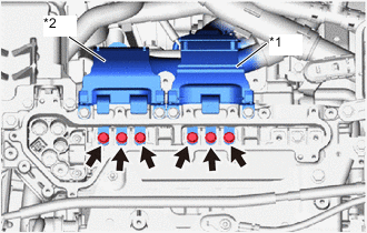
*1 FC air compressor motor cable *2 Drive Motor Cable Disconnect the FC air compressor motor cable and drive motor cable from the inverter with converter assembly.
-
*1 High voltage terminal Using a megohmmeter set to 500 V, measure the resistance according to the value(s) in the table below.
Note
Be sure to set the megohmmeter to 500 V when performing this test. Using a setting higher than 500 V can result in damage to the component being inspected.
Standard Resistance Tester Connection Condition Specified Condition High voltage terminal - Body ground Power switch off 1 MΩ or higher Tech Tips
When performing the inspection, the only high voltage component that can be connected to the inverter with converter assembly is the FC inverter input junction assembly.
Result Proceed to OK NG
NG
CHECK INVERTER WITH CONVERTER ASSEMBLY Click here
OK
-
-
REPLACE FC CONVERTER ASSEMBLY
Result Proceed to NEXT
NEXT
PERFORM CONFIRMATION AFTER REPLACING PARTS Click here
-
CHECK INVERTER WITH CONVERTER ASSEMBLY
CAUTION:
Be sure to wear insulated gloves.
-
Check that the service plug grip is not installed to FC stack assembly and EV battery.
Note
After removing the service plug grip, do not turn the power switch on (READY), unless instructed by the repair manual because this may cause a malfunction.
-
Disconnect the FC inverter input junction assembly from the inverter with converter assembly.
-
*1 High voltage terminal Using a megohmmeter set to 500 V, measure the resistance according to the value(s) in the table below.
Note
Be sure to set the megohmmeter to 500 V when performing this test. Using a setting higher than 500 V can result in damage to the component being inspected.
Standard Resistance Tester Connection Condition Specified Condition High voltage terminal - Body ground Power switch off 1 MΩ or higher Tech Tips
Perform this inspection with the drive motor cable, FC air compressor motor cable, FC inverter input junction assembly, FC converter power outlet cable and No. 3 motor wire (air conditioning harness) disconnected from the inverter with converter assembly.
Result Proceed to OK NG
NG
REPLACE INVERTER WITH CONVERTER ASSEMBLY Click here
OK
-
-
REPLACE FC INVERTER INPUT JUNCTION ASSEMBLY
Result Proceed to NEXT
NEXT
PERFORM CONFIRMATION AFTER REPLACING PARTS Click here
-
REPLACE INVERTER WITH CONVERTER ASSEMBLY
Result Proceed to NEXT
NEXT
PERFORM CONFIRMATION AFTER REPLACING PARTS Click here
-
REPLACE FC STACK ASSEMBLY
Result Proceed to NEXT
NEXT
PERFORM CONFIRMATION AFTER REPLACING PARTS Click here
-
CHECK FC CONVERTER POWER OUTLET CABLE
CAUTION:
Be sure to wear insulated gloves.
-
Check that the service plug grip is not installed to FC stack assembly and EV battery.
Note
After removing the service plug grip, do not turn the power switch on (READY), unless instructed by the repair manual because this may cause a malfunction.
-
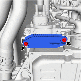
Remove the front FC converter service hole cover from the FC converter assembly.
-
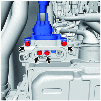
Disconnect the FC converter power outlet cable from the FC converter assembly.
-
*1 Shield Ground *a FC Converter Power Outlet Cable
(Inverter with Converter Assembly Side)
Using a megohmmeter set to 500 V, measure the resistance according to the value(s) in the table below.
Note
Be sure to set the megohmmeter to 500 V when performing this test. Using a setting higher than 500 V can result in damage to the component being inspected.
Standard Resistance Tester Connection Condition Specified Condition p1-1 (F-N) - Body ground and shielded wire ground Power switch off 10 MΩ or higher p1-2 (F-VN) - Body ground and shielded wire ground Power switch off 10 MΩ or higher Result Proceed to OK NG
NG
REPLACE FC CONVERTER POWER OUTLET CABLE Click here
OK
-
-
REPLACE FC CONVERTER ASSEMBLY
Result Proceed to NEXT
NEXT
PERFORM CONFIRMATION AFTER REPLACING PARTS Click here
-
REPLACE FC CONVERTER POWER OUTLET CABLE
Result Proceed to NEXT
NEXT
PERFORM CONFIRMATION AFTER REPLACING PARTS Click here
-
REPLACE ELECTRIC HEATER SUB-ASSEMBLY
Result Proceed to NEXT
NEXT
PERFORM CONFIRMATION AFTER REPLACING PARTS Click here
-
REPLACE FC WATER AND HYDROGEN PUMP INVERTER ASSEMBLY
Result Proceed to NEXT
NEXT
PERFORM CONFIRMATION AFTER REPLACING PARTS Click here
-
CHECK NO. 3 MOTOR WIRE
CAUTION:
Be sure to wear insulated gloves.
-
Check that the service plug grip is not installed to FC stack assembly and EV battery.
Note
After removing the service plug grip, do not turn the power switch on (READY), unless instructed by the repair manual because this may cause a malfunction.
-
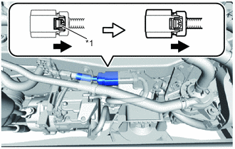
*1 Green Lock Disconnect the No. 3 motor cable from the compressor with motor assembly.
-
*1 Shield Ground *a No. 3 Motor Wire
(Inverter with Converter Assembly Side)
Using a megohmmeter set to 500 V, measure the resistance according to the value(s) in the table below.
Note
Be sure to set the megohmmeter to 500 V when performing this test. Using a setting higher than 500 V can result in damage to the component being inspected.
Standard Resistance Tester Connection Condition Specified Condition E4-1 (ACPE) - Body ground and shielded wire ground Power switch off 10 MΩ or higher E4-2 (ACPB) - Body ground and shielded wire ground Power switch off 10 MΩ or higher Result Proceed to OK NG
NG
REPLACE NO. 3 MOTOR WIRE Click here
OK
-
-
GO TO AIR CONDITIONING SYSTEM (P0AA6-611)
Result Proceed to NEXT
NEXT
PERFORM CONFIRMATION AFTER REPLACING PARTS Click here
-
REPLACE NO. 3 MOTOR WIRE
Result Proceed to NEXT
NEXT
PERFORM CONFIRMATION AFTER REPLACING PARTS Click here
-
CHECK FRAME WIRE
CAUTION:
Be sure to wear insulated gloves.
-
Check that the service plug grip is not installed to FC stack assembly and EV battery.
Note
After removing the service plug grip, do not turn the power switch on (READY), unless instructed by the repair manual because this may cause a malfunction.
-
Remove the No. 4 EV battery shield panel.
-
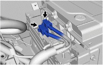
Disconnect the frame wire connectors from the EV battery junction block assembly.
Tech Tips
Make sure that no foreign matter has entered or contaminated the frame wire.
-
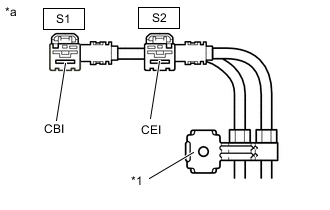
*1 Shield Ground *a Frame Wire
(EV Battery Junction Block Assembly Side)
Using a megohmmeter set to 500 V, measure the resistance according to the value(s) in the table below.
Note
Be sure to set the megohmmeter to 500 V when performing this test. Using a setting higher than 500 V can result in damage to the component being inspected.
Standard Resistance Tester Connection Condition Specified Condition S1-1 (CBI) - Body ground and shielded wire ground Power switch off 10 MΩ or higher S2-1 (CEI) - Body ground and shielded wire ground Power switch off 10 MΩ or higher Tech Tips
Visually inspect the frame wire for damage. If there is any damage, then this is the likely cause of low insulation resistance.
Result Proceed to OK NG
NG
REPLACE FRAME WIRE Click here
OK
-
-
REPLACE EV BATTERY JUNCTION BLOCK ASSEMBLY
Result Proceed to NEXT
NEXT
PERFORM CONFIRMATION AFTER REPLACING PARTS Click here
-
REPLACE FRAME WIRE
Result Proceed to NEXT
NEXT
PERFORM CONFIRMATION AFTER REPLACING PARTS Click here