HYBRID CONTROL SYSTEM, Diagnostic DTC:P0AA1-233
| DTC Code | DTC Name |
|---|---|
| P0AA1-233 | Battery Positive Contactor Circuit Stuck Closed |
DTC SUMMARY
-
MALFUNCTION DESCRIPTION
The EV control ECU detects a stuck closed malfunction of a system main relay on the EV battery positive side and negative side.
The cause of this malfunction may be one of the following:
-
Voltage sensor (VH) malfunction
-
Motor generator control ECU (MG ECU) malfunction
-
Communication (wire harness) malfunction
Inside of inverter voltage sensor (VH) circuit malfunction
-
EV battery junction block assembly malfunction
High voltage system malfunction
-
EV control ECU malfunction
-
EV battery junction block assembly malfunction
-
Low voltage wire harness malfunction
-
Low voltage connector malfunction
Low-voltage circuit (12 V) malfunction
-
DESCRIPTION
Refer to the description for DTC P0AE6-225.
This circuit uses the EV control ECU to monitor the system main relays and stops the system if a malfunction is detected in the relays, because it may be impossible to shut off the high-voltage system if any of the relays becomes stuck.
| DTC No. | Detection Item | DTC Detection Condition | Trouble Area | Warning Indicate |
|---|---|---|---|---|
| P0AA1-233 | Battery Positive Contactor Circuit Stuck Closed | System main relay stuck closed malfunction (EV battery positive (+) and negative (-) terminal side) (1 trip detection logic) |
|
Master Warning Light: Comes on |
| DTC No. | Data List |
|---|---|
| P0AA1-233 |
|
The following items can be helpful when performing repairs:
-
SMRP Status
-
SMRB Status
-
SMRG Status
Data List
WIRING DIAGRAM
Refer to the wiring diagram for the EV battery high-voltage line circuit.
CAUTION / NOTICE / HINT
CAUTION:
-
When troubleshooting DTC P0AA1-233, use either a tool wrapped with vinyl insulation tape or an insulated tool (It is extremely dangerous when a high-voltage charge passes through a non-insulated tool causing a short).
-


Before the following operations are conducted, take precautions to prevent electric shock by turning the power switch off, wearing insulated gloves, and removing the service plug grips from both FC stack assembly and EV battery.
-
Inspecting the high-voltage system
-
Disconnecting the low voltage connector of the inverter with converter assembly
-
Disconnecting the low voltage connector of the EV battery
-
Disconnecting the low voltage connector of the FC stack assembly
-
Disconnecting the low voltage connector of the FC converter assembly
Tech Tips
No removal order is specified for the service plug grips of the FC stack assembly and EV battery.
-

After removing the service plug grip from the EV battery, put it in your pocket to prevent other technicians from accidentally reconnecting it while you are working on the high-voltage system. After removing the service grip from the FC stack assembly, store it in a safe location and use the "HIGH-VOLTAGE, DO NOT TOUCH" sign to notify other technicians that you are working on the high-voltage system.
-

*a Without waiting for 10 minutes After removal of the service plug grips of both FC stack assembly and EV battery, wait for at least 10 minutes before touching the high-voltage connectors and terminals. After waiting for 10 minutes, check the voltage at the terminals in the inspection point in the inverter with converter assembly. The voltage should be 0 V before beginning work.
Tech Tips
At least 10 minutes are necessary to discharge the high-voltage capacitors inside the inverter with converter assembly and FC stack assembly.
Note
-
After turning the power switch off, waiting time may be required before disconnecting the cable from the negative (-) auxiliary battery terminal. Therefore, make sure to read the disconnecting the cable from the negative (-) auxiliary battery terminal notices before proceeding with work.
-
If P0AA1-233 is output, remove the service plug grip (for EV) and keep it removed until repairs have been completed. If the service plug grip (for EV) is not removed, the EV battery will gradually be discharged, and SOC will decrease.
-
Before performing repairs, clearing the DTCs or disconnecting and reconnecting the auxiliary battery terminal and then turning the power switch on (READY) could cause a malfunction, so make sure not to turn the power switch on (READY).
-
When reinstalling the service plug grip to the FC stack assembly or the EV battery, slide the lever of the service plug until the letters "UNLOCK" are completely hidden, and insert it firmly.
-
When the vehicle is parked with the power switch off, if the FC control ECU judges that the FC stack temperature will go below 0°C (32°F), it activates the FC air compressor, hydrogen pump and FC cooling water pump for a maximum of 180 seconds and drains water from the FC stack assembly. When performing inspection or repairs with the power switch off (not on (IG) or on (READY)), disconnect the cable from the negative (-) auxiliary battery terminal before performing work (If the auxiliary battery voltage is needed to conduct inspection, warm up the FC system beforehand).
Tech Tips
-
If DTC P0AA1-233 is output, the power switch cannot be turned on (READY).
-
After the repair, clear the DTCs and perform the following procedure to check that DTCs are not output.
-
Turn the power switch off and wait for 30 seconds or more.
-
Turn the power switch on (READY) and wait for 30 seconds or more.
-
Turn the power switch off and wait for 30 seconds or more.
PROCEDURE
-
CHECK DTC OUTPUT (EV)
-
Connect the GTS to the DLC3.
-
Turn the power switch on (IG).
-
Enter the following menus: Powertrain / EV / Trouble Codes.
-
Check for DTCs.
Powertrain > EV > Trouble CodesResult Result Proceed to P0AA1-233 only is output, or DTCs except the ones in the table below are also output. A Any of the following DTCs including pending DTCs are also output. B Malfunction Content Relevant DTC Microcomputer malfunction P0A1B-163, 164, 168, 193, 511, 512, 661, 786, 794, 795, 796 Drive Motor "A" Control Module P0A1D-148 EV Control Module P1D8F-474, 475, 476, 477, 479, 481, 482, 483, 484 FC Air Compressor Motor "A" Control Module P324E-788 Motor CPU Power Relay Sense Circuit Intermittent No Continuity Power source circuit malfunction P2511-149 EV CPU Power Relay Sense Circuit Intermittent No Continuity Communication system malfunction U0110 (all INF codes)*1 Lost Communication with Drive Motor Control Module "A" Sensor and actuator circuit malfunction P0A3F-243 Drive Motor "A" Position Sensor Circuit P0A40-500 Drive Motor "A" Position Sensor Circuit Range/Performance P0A41-245 Drive Motor "A" Position Sensor Circuit Low P1D75-450 FC Air Compressor Motor "A" Position Sensor Circuit P1D76-450 FC Air Compressor Motor "A" Position Sensor Circuit Range/Performance P1D77-450 FC Air Compressor Motor "A" Position Sensor Circuit Low P0A78-266, 267, 586 FC Air Compressor Motor "A" Position Sensor Circuit Low P0A94-442 Boosting Converter Performance P0ADC-226 Battery Positive Contactor Control Circuit High P0AE0-228 Battery Negative Contactor Control Circuit High P0AE7-224 Battery Precharge Contactor Control Circuit High P1E15-450*2 FC Stack Positive Relay Stuck Closed P1E17-450 FC Stack Negative Relay Stuck Closed P0C76-523 EV Battery System Discharge Time Too Long System malfunction P3004-132 High Voltage Power Resource Tech Tips
-
*1: If any INF codes are output for this DTC, refer to the corresponding diagnostic procedure.
-
*2: When welding has occurred at both poles of the FC relay, DTC P0AA1-233 may be output.
-
P0AA1-233 may be output as a result of the malfunction indicated by the DTCs above.
-
The chart above is listed in inspection order of priority.
-
Check DTCs that are output at the same time by following the listed order. (The main cause of the malfunction can be determined without performing unnecessary inspections.)
-
-
Turn the power switch off.
B 
GO TO DTC CHART (EV CONTROL SYSTEM)
A 
-
-
CHECK FREEZE FRAME DATA (EV)
-
Connect the GTS to the DLC3.
-
Turn the power switch on (IG).
-
Enter the following menus: Powertrain / EV / Trouble Codes.
-
Read the freeze frame data of DTC P0AA1-233.
Tech Tips
In the freeze frame data, read the items "VH-Voltage after Boosting" and "VL-Voltage before Boosting".
Result Result Proceed to "VH-Voltage after Boosting" minus "VL-Voltage before Boosting" is 100 V or less. A The preceding condition is not satisfied. B Tech Tips
If VH-Voltage after Boosting is output even when an off command is being sent to the system main relay (positive side), P0AA1-233 is output. If the difference between the "VL-Voltage before Boosting" and the "VH-Voltage after Boosting" is large, it is determined that there is an inverter (VH sensor) malfunction.
-
Turn the power switch off.
B
REPLACE INVERTER WITH CONVERTER ASSEMBLY
A
-
-
CHECK CONNECTOR CONNECTION CONDITION (EV CONTROL ECU ASSEMBLY CONNECTOR)
Result Proceed to OK NG
-
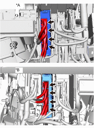
*A for LHD *B for RHD Check the connector connections and contact pressure of the relevant terminals for the EV control ECU connectors.
OK The connectors are connected securely and there are no contact pressure problems. Result Proceed to OK NG
OK 
GO TO STEP 5 Click here
NG
-
-
CONNECT SECURELY
Result Proceed to NEXT
NEXT
-
CHECK CONNECTOR CONNECTION CONDITION (FLOOR WIRE CONNECTOR)
-
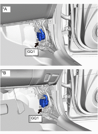
*A for LHD *B for RHD Check the connector connections and contact pressure of the relevant terminals for the GQ1 floor wire connector.
OK The connectors are connected securely and there are no contact pressure problems. Result Proceed to OK NG
OK
GO TO STEP 7 Click here
NG
-
-
CONNECT SECURELY
Result Proceed to NEXT
NEXT
-
CHECK CONNECTOR CONNECTION CONDITION (EV BATTERY JUNCTION BLOCK ASSEMBLY CONNECTOR)
CAUTION:
Be sure to wear insulated gloves.
-
Check that the service plug grip is not installed to FC stack assembly and EV battery.
Note
After removing the service plug grip, do not turn the power switch on (READY), unless instructed by the repair manual because this may cause a malfunction.
-
Remove the No. 4 EV battery shield panel.
-
Check the connection condition of the EV battery junction block connector and the contact pressure of each terminal. Check the terminals for deformation, and check the connector for water ingress and foreign matter.
OK The connectors are connected securely and there are no contact pressure problems. -
Install the No. 4 EV battery shield panel.
Result Proceed to OK NG
OK
GO TO STEP 9 Click here
NG
-
-
CONNECT SECURELY
Result Proceed to NEXT
NEXT
-
CHECK GROUND WIRE CONNECTION CONDITION (SMR ACTIVATION LOW-VOLTAGE CIRCUIT)
-
Check the installation condition of the ground wires GA, GD and QB.
OK The ground wires GA, GD and QB are securely installed. Result Proceed to OK NG
OK
GO TO STEP 11 Click here
NG
-
-
CONNECT SECURELY
Result Proceed to NEXT
NEXT
-
CHECK HARNESS AND CONNECTOR (EV CONTROL ECU - EV BATTERY JUNCTION BLOCK ASSEMBLY)
CAUTION:
Be sure to wear insulated gloves.
-
Check that the service plug grip is not installed to FC stack assembly and EV battery.
Note
After removing the service plug grip, do not turn the power switch on (READY), unless instructed by the repair manual because this may cause a malfunction.
-
Remove the No. 4 EV battery shield panel.
-
Disconnect the EV junction block assembly connector.
-
Disconnect the EV control ECU connector.
-
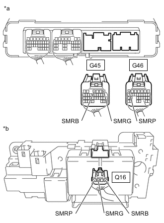
*a Rear view of wire harness connector
(to EV Control ECU)
*b Rear view of wire harness connector
(to EV Battery Junction Block Assembly)
Measure the resistance according to the value(s) in the table below.
Standard Resistance Tester Connection Condition Specified Condition G45-4 (SMRB) - Q16-1 (SMRB) Power switch off Below 1 Ω G45-1 (SMRG) - Q16-3 (SMRG) Power switch off Below 1 Ω G46-7 (SMRP) - Q16-4 (SMRP) Power switch off Below 1 Ω G45-4 (SMRB) and Q16-1 (SMRB) - Body ground and other terminals Power switch off 10 kΩ or higher G45-1 (SMRG) and Q16-3 (SMRG) - Body ground and other terminals Power switch off 10 kΩ or higher G46-7 (SMRP) and Q16-4 (SMRP) - Body ground and other terminals Power switch off 10 kΩ or higher -
Reconnect the EV control ECU connector.
-
Reconnect the EV junction block assembly connector.
-
Install the No. 4 EV battery shield panel.
Result Proceed to OK NG
OK
GO TO STEP 13 Click here
NG
-
-
REPAIR OR REPLACE HARNESS OR CONNECTOR
Result Proceed to NEXT
NEXT
-
CHECK HARNESS AND CONNECTOR (EV BATTERY JUNCTION BLOCK ASSEMBLY - BODY GROUND)
CAUTION:
Be sure to wear insulated gloves.
-
Check that the service plug grip is not installed to FC stack assembly and EV battery.
Note
After removing the service plug grip, do not turn the power switch on (READY), unless instructed by the repair manual because this may cause a malfunction.
-
Remove the No. 4 EV battery shield panel.
-
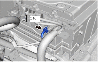
Disconnect the EV battery junction block assembly connector.
-
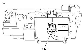
*a Rear view of wire harness connector
(to EV Battery Junction Block Assembly)
Measure the resistance according to the value(s) in the table below.
Standard Resistance Tester Connection Condition Specified Condition Q16-2 (GND) - Body ground Power switch off Below 1 Ω -
Reconnect the EV battery junction block assembly connector.
-
Install the No. 4 EV battery shield panel.
Result Proceed to OK NG
OK
GO TO STEP 15 Click here
NG
-
-
REPAIR OR REPLACE HARNESS OR CONNECTOR
Result Proceed to NEXT
NEXT
-
INSPECT EV BATTERY JUNCTION BLOCK ASSEMBLY (SMRB, SMRG, SMRP)
CAUTION:
Be sure to wear insulated gloves.
-
Check that the service plug grip is not installed to FC stack assembly and EV battery.
Note
After removing the service plug grip, do not turn the power switch on (READY), unless instructed by the repair manual because this may cause a malfunction.
-
Remove the No. 4 EV battery shield panel.
-
Disconnect the EV battery junction block assembly connector.
-
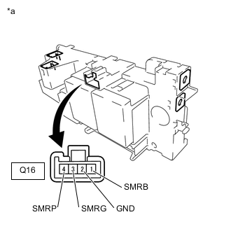
*a Component without harness connected
(EV Battery Junction Block Assembly)
Measure the resistance according to the value(s) in the table below.
Standard Resistance Tester Connection Condition Specified Condition Q16-1 (SMRB) - Q16-2 (GND) -40 to 80°C (-40 to 176°F) 25.0 to 59.0 Ω Q16-3 (SMRG) - Q16-2 (GND) -40 to 80°C (-40 to 176°F) 25.0 to 59.0 Ω Q16-4 (SMRP) - Q16-2 (GND) -40 to 80°C (-40 to 176°F) 112 to 274 Ω -
Reconnect the EV battery junction block assembly connector.
-
Install the No. 4 EV battery shield panel.
Result Proceed to OK NG
NG
REPLACE EV BATTERY JUNCTION BLOCK ASSEMBLY Click here
OK
-
-
CHECK EV BATTERY JUNCTION BLOCK ASSEMBLY (SMRP, SMRB, SMRG)
CAUTION:
Be sure to wear insulated gloves.
-
Check that the service plug grip is not installed to FC stack assembly and EV battery.
Note
After removing the service plug grip, do not turn the power switch on (READY), unless instructed by the repair manual because this may cause a malfunction.
-
Remove the No. 1 EV battery shield sub-assembly.
-
Disconnect the frame wire connector from the EV battery junction block assembly.
-
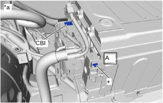
Measure the resistance according to the value(s) in the table below.
Standard Resistance (SMRB) Tester Connection Condition Specified Condition CBI - A-1 (+) Power switch off 10 kΩ or higher Tech Tips
-
If a system main relay is stuck closed, inspect the EV battery junction block assembly without removing it from the vehicle, in order to keep the relay closed.
-
If the result of reading the freeze frame data is A, the EV battery junction block assembly must be replaced. Measuring resistance can determine that this is either a present or past malfunction.
-
-
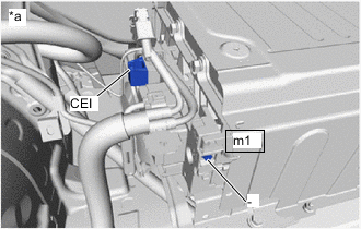
*a EV Battery Junction Block Assembly Measure the resistance according to the value(s) in the table below.
Standard Resistance (SMRG, SMRP) Tester Connection Condition Specified Condition CEI - m1-1 (-) Power switch off 10 kΩ or higher Tech Tips
-
If a system main relay is stuck closed, inspect the EV battery junction block assembly without removing it from the vehicle, in order to keep the relay closed.
-
If the result of reading the freeze frame data is A, the EV battery junction block assembly must be replaced. Measuring resistance can determine that this is either a present or past malfunction.
-
If the resistance is between 28.5 and 31.5 Ω, it can be determined that SMRP is stuck closed.
-
-
Reconnect the frame wire connector to the EV battery junction block assembly.
-
Install the No. 1 EV battery shield sub-assembly.
Result Proceed to OK NG
NG
REPLACE EV BATTERY JUNCTION BLOCK ASSEMBLY Click here
OK
-
-
REPLACE EV BATTERY JUNCTION BLOCK ASSEMBLY
Result Proceed to NEXT
NEXT
GO TO STEP 20 Click here
-
REPLACE EV BATTERY JUNCTION BLOCK ASSEMBLY
Result Proceed to NEXT
NEXT
GO TO STEP 20 Click here
-
REPLACE EV BATTERY JUNCTION BLOCK ASSEMBLY
Result Proceed to NEXT
NEXT
-
CHECK EV CONTROL ECU (CHECK FOR NORMAL OPERATION)
-
Install the FC stack service plug grip and service plug grip (for EV).
-
Turn the power switch on (IG).
-
Clear the DTCs.
Powertrain > EV > Clear DTCs -
Turn the power switch off and wait for 30 seconds or more.
-
Turn the power switch on (READY).
-
Enter the following menus: Powertrain / EV / Data List / VL-Voltage before Boosting, VB-Battery Voltage.
-
According to the display on the GTS, read the Data List and monitor the values of "VB-Battery Voltage" and "VL-Voltage before Boosting" for 3 minutes.
Powertrain > EV > Data ListTester Display VL-Voltage before Boosting VB-Battery Voltage Result Result Proceed to Difference between "VB-Battery Voltage" and "VL-Voltage before Boosting" is always less than 100 V. A Difference between "VB-Battery Voltage" and "VL-Voltage before Boosting" is 100 V or more. B -
Turn the power switch off.
A
COMPLETED
B
REPLACE EV CONTROL ECU AND EV BATTERY JUNCTION BLOCK ASSEMBLY EV control ECU: REPLACE EV CONTROL ECU AND EV BATTERY JUNCTION BLOCK ASSEMBLY Click here
REPLACE EV CONTROL ECU AND EV BATTERY JUNCTION BLOCK ASSEMBLY EV battery junction block assembly: REPLACE EV CONTROL ECU AND EV BATTERY JUNCTION BLOCK ASSEMBLY Click here -