HYBRID CONTROL SYSTEM DIAGNOSIS SYSTEM
-
DESCRIPTION
-
The EV control ECU has a self-diagnosis system. If the computer, hybrid control system, or a component is not working properly, the ECU records the conditions that relate to the fault. The ECU also illuminates the master warning light in the combination meter assembly and provides other appropriate messages on the multi-information display, such as the hybrid control system warning message, EV battery warning message, or discharge warning message.
Tech Tips
The master warning light will illuminate when the hybrid control system is malfunctioning.
-
In situations when the vehicle is driven under heavy load or other operating conditions which make it difficult for the FC system to provide optimal output to the vehicle, the output power may be temporarily restricted. When output power is restricted due to high FC system temperature, the power restriction indicator will illuminate in amber, and when due to low FC system temperature it will illuminate in blue.
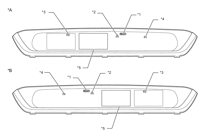
*A for LHD *B for RHD *1 READY Indicator *2 Master Warning Light *3 Power restriction Indicator *4 Charging System Warning Light *5 Multi-information Display - - -
-
2 TRIP DETECTION LOGIC
-
When a malfunction is first detected, the malfunction is temporarily stored in the EV control ECU memory (1st trip). If the same malfunction is detected during the next drive cycle, the master warning light is illuminated (2nd trip).
-
-
FREEZE FRAME DATA
-
The EV control ECU records vehicle and driving condition information as freeze frame data the moment a DTC is stored. When troubleshooting, freeze frame data can be helpful in determining whether the vehicle was moving or stationary, whether the hybrid control system was warmed up or not, as well as other data recorded at the time of a malfunction.
-
-
AUXILIARY BATTERY VOLTAGE
-
If voltage is below 11 V, replace or recharge the auxiliary battery.
Note
After turning the power switch off, waiting time may be required before disconnecting the cable from the negative (-) auxiliary battery terminal. Therefore, make sure to read the disconnecting the cable from the negative (-) auxiliary battery terminal notices before proceeding with work.
-
-
RELEVANT SYSTEMS CHECK
The inspection areas and outline of the inspection for each circuit are listed below.

Inspection Details of Relevant Systems System to be Inspected Malfunction Possibility Inspection Content Cooling System Temperature abnormally high
-
Grille blockage
-
Whether coolant is present
-
Whether there is a possibility that coolant was frozen when malfunction occurs
-
Cooling hose blockage
-
Radiator fan operation
Shutdown Signal System Shutdown signal
-
Open or short circuit in shutdown signal communication line between EV control ECU and motor generator control ECU
-
Short in shutdown signal communication line between FC boost control ECU and EV control ECU.
Inverter Low-voltage Circuit Power supply voltage from +B or communication between EV control ECU and motor generator control ECU
-
Open or short circuit in communication line between EV control ECU and motor generator control ECU
-
Open or short circuit in the +B or ground lines
-
Fuse is blown
EV Battery High-voltage Line Circuit High voltage power supply from EV battery
-
Open or short circuit in the system main relay, connectors or cables
Motor Resolver Circuit Drive motor resolver signal
-
Open or short circuit in the drive motor resolver, connectors or cables
FC Air Compressor Resolver Circuit FC air compressor motor resolver signal
-
Open or short circuit in the FC air compressor motor resolver, connectors or cables
Motor High-voltage Circuit Drive motor output
-
Open or short circuit in the drive motor, connectors or cables
FC Air Compressor High-voltage Circuit FC air compressor output
-
Open or short circuit in the FC air compressor assembly, connectors or cables
-
-
DTC PRIORITY LEVEL AND TROUBLE AREAS
-
Each DTC diagnostic procedure for the EV control system consists of a combination of the relevant system (circuit) inspections.
-
When multiple DTCs are output, performing each diagnostic procedure in order of priority can lead to a more accurate diagnosis.

Diagnostic priority order and areas for inspection, related GTS custom lists DTC No. Detection Item Order of Priority Inspection Pattern GTS Custom Lists*1 1 2 3 4 5 Microcomputer Malfunction Power Source Circuit Malfunction Communication System Malfunction Sensor and Actuator Circuit Malfunction System Malfunction P0516-769 Battery Temperature Sensor Circuit Low - - - ○ - - - P0517-770 Battery Temperature Sensor Circuit High - - - ○ - - - P0560-117 System Voltage - ○ - - - - - P060B-134 Internal Control Module A/D Processing Performance ○ - - - - - - P060B-135 Internal Control Module A/D Processing Performance ○ - - - - - - P060B-570 Internal Control Module A/D Processing Performance ○ - - - - - - P0617-142 Starter Relay Circuit High - - - ○ - - - P062F-143 Internal Control Module EEPROM Error ○ - - - - - - P062F-252 Internal Control Module EEPROM Error ○ - - - - - - P0630-804 VIN Not Programmed or Mismatch - ECM/PCM - - - - - - - P082B-575 Gear Lever X Position Circuit Low - - - ○ - - 10 P082C-576 Gear Lever X Position Circuit High - - - ○ - - 10 P082E-571 Gear Lever Y Position Circuit Low - - - ○ - - 10 P082F-572 Gear Lever Y Position Circuit High - - - ○ - - 10 P0851-579 Park/Neutral Switch Input Circuit Low - - - ○ - - - P0852-580 Park/Neutral Switch Input Circuit High - - - ○ - - - P085D-582 Gear Shift Control Module "A" Performance - - ○ - - - - P085D-599 Gear Shift Control Module "A" Performance - - ○ - - - - P0861-597 Gear Shift Control Module "A" Communication Circuit Low - - - ○ - - - P0862-598 Gear Shift Control Module "A" Communication Circuit High - - - ○ - - - P0A01-726 Motor Electronics Coolant Temperature Sensor Circuit Range/Performance - - - ○ - B 4 P0A02-719 Motor Electronics Coolant Temperature Sensor Circuit Low - - - ○ - - - P0A03-720 Motor Electronics Coolant Temperature Sensor Circuit High - - - ○ - - - P0A04-725 Motor Electronics Coolant Temperature Sensor Circuit Intermittent - - - ○ - B 4 P0A08-264 DC/DC Converter Status Circuit - - - - ○ - 8 P0A09-265 DC/DC Converter Status Circuit Low - - - ○ - - - P0A09-591 DC/DC Converter Status Circuit Low - - - ○ - - - P0A0D-350 High Voltage System Interlock Circuit High - - - - ○ - - P0A0D-351 High Voltage System Interlock Circuit High - - - - ○ - - P0A10-263 DC/DC Converter Status Circuit High - - - ○ - - - P0A10-592 DC/DC Converter Status Circuit High - - - ○ - - - P0A1B-163 Drive Motor "A" Control Module - ○ - - - - - P0A1B-164 Drive Motor "A" Control Module - ○ - - - - - P0A1B-168 Drive Motor "A" Control Module ○ - - - - - - P0A1B-192 Drive Motor "A" Control Module ○ - - - - - - P0A1B-193 Drive Motor "A" Control Module ○ - - - - - - P0A1B-198 Drive Motor "A" Control Module ○ - - - - - - P0A1B-511 Drive Motor "A" Control Module - ○ - - - - - P0A1B-512 Drive Motor "A" Control Module - ○ - - - - - P0A1B-661 Drive Motor "A" Control Module ○ - - - - - - P0A1B-786 Drive Motor "A" Control Module ○ - - - - - - P0A1B-794 Drive Motor "A" Control Module ○ - - - - - - P0A1B-795 Drive Motor "A" Control Module ○ - - - - - - P0A1B-796 Drive Motor "A" Control Module ○ - - - - - - P0A1D-144 EV Control Module ○ - - - - - - P0A1D-148 EV Control Module ○ - - - - - - P0A1D-162 EV Control Module ○ - - - - - - P0A1D-187 EV Control Module ○ - - - - - - P0A1D-721 EV Control Module ○ - - - - - - P0A1D-722 EV Control Module ○ - - - - - - P0A1D-723 EV Control Module ○ - - - - - - P0A1D-787 EV Control Module ○ - - - - - - P0A1D-818 EV Control Module ○ - - - - - - P0A1D-821 EV Control Module ○ - - - - - - P0A1D-822 EV Control Module ○ - - - - - - P0A1D-823 EV Control Module ○ - - - - - - P0A2B-250 Drive Motor "A" Temperature Sensor Circuit Range/Performance - - - ○ - - 6 P0A2C-247 Drive Motor "A" Temperature Sensor Circuit Low - - - ○ - - - P0A2D-249 Drive Motor "A" Temperature Sensor Circuit High - - - ○ - - - P0A2E-248 Drive Motor "A" Temperature Sensor Circuit Intermittent - - - ○ - - 6 P0A3F-243 Drive Motor "A" Position Sensor Circuit - - - ○ - L 6 P0A40-500 Drive Motor "A" Position Sensor Circuit Range/Performance - - - ○ - L 6 P0A41-245 Drive Motor "A" Position Sensor Circuit Low - - - ○ - L - P0A51-174 Drive Motor "A" Current Sensor Circuit - - - ○ - - - P0A60-288 Drive Motor "A" Phase V Current - - - ○ - A - P0A60-290 Drive Motor "A" Phase V Current - - - ○ - A - P0A60-294 Drive Motor "A" Phase V Current - - - ○ - A - P0A60-501 Drive Motor "A" Phase V Current - - - ○ - A - P0A63-296 Drive Motor "A" Phase W Current - - - ○ - A - P0A63-298 Drive Motor "A" Phase W Current - - - ○ - A - P0A63-302 Drive Motor "A" Phase W Current - - - ○ - A - P0A63-502 Drive Motor "A" Phase W Current - - - ○ - A - P0A78-113 Drive Motor "A" Inverter Performance - - - - ○ D 6 P0A78-121 Drive Motor "A" Inverter Performance - - - - ○ J 6 P0A78-128 Drive Motor "A" Inverter Performance - - - - ○ D 6 P0A78-266 Drive Motor "A" Inverter Performance - - - - ○ - 6 P0A78-267 Drive Motor "A" Inverter Performance - - - - ○ - 6 P0A78-279 Drive Motor "A" Inverter Performance - - - - ○ A 6 P0A78-282 Drive Motor "A" Inverter Performance - - - - ○ A 6 P0A78-284 Drive Motor "A" Inverter Performance - - - - ○ F 6 P0A78-286 Drive Motor "A" Inverter Performance - - - - ○ F 6 P0A78-287 Drive Motor "A" Inverter Performance - - - - ○ A 6 P0A78-306 Drive Motor "A" Inverter Performance - - - - ○ N 6 P0A78-503 Drive Motor "A" Inverter Performance - - - - ○ A 6 P0A78-504 Drive Motor "A" Inverter Performance - - - - ○ L 6 P0A78-505 Drive Motor "A" Inverter Performance - - - - ○ A 6 P0A78-506 Drive Motor "A" Inverter Performance - - - - ○ L 6 P0A78-510 Drive Motor "A" Inverter Performance - - - - ○ A 6 P0A78-586 Drive Motor "A" Inverter Performance - - - - ○ - 6 P0A78-806 Drive Motor "A" Inverter Performance - - - - ○ C 6 P0A78-807 Drive Motor "A" Inverter Performance - - - - ○ A 6 P0A78-808 Drive Motor "A" Inverter Performance - - - - ○ L 6 P0A90-251 Drive Motor "A" Performance - - - - ○ N 6 P0A90-509 Drive Motor "A" Performance - - - - ○ N 6 P0A93-346 Inverter Cooling System Performance - - - ○ - B 4 P0A94-127 Boosting Converter Performance - - - - ○ J 4 P0A94-172 Boosting Converter Performance - - - - ○ H 4 P0A94-442 Boosting Converter Performance - - - - ○ A 4 P0A94-547 Boosting Converter Performance - - - - ○ A 4 P0A94-548 Boosting Converter Performance - - - - ○ A 4 P0A94-549 Boosting Converter Performance - - - - ○ C 4 P0A94-550 Boosting Converter Performance - - - - ○ A 4 P0A94-553 Boosting Converter Performance - - - - ○ I 4 P0A94-554 Boosting Converter Performance - - - - ○ A 4 P0A94-555 Boosting Converter Performance - - - - ○ A 4 P0A94-556 Boosting Converter Performance - - - - ○ C 4 P0A94-557 Boosting Converter Performance - - - - ○ I 4 P0A94-585 Boosting Converter Performance - - - - ○ - 4 P0A94-587 Boosting Converter Performance - - - - ○ - 4 P0A94-589 Boosting Converter Performance - - - - ○ - 4 P0A94-590 Boosting Converter Performance - - - - ○ - 4 P0AA1-231 Battery Positive Contactor Circuit Stuck Closed - - - - ○ - 3 P0AA1-233 Battery Positive Contactor Circuit Stuck Closed - - - - ○ - 3 P0AA4-232 Battery Negative Contactor Circuit Stuck Closed - - - - ○ - 3 P0AA6-485 EV Battery Voltage System Isolation Fault - - - - ○ - 3 P0AA6-486 EV Battery Voltage System Isolation Fault - - - - ○ - 3 P0AA6-487 EV Battery Voltage System Isolation Fault - - - - ○ - 3 P0AA6-488 EV Battery Voltage System Isolation Fault - - - - ○ - 3 P0AA6-526 EV Battery Voltage System Isolation Fault - - - - ○ - 3 P0AA6-611 EV Battery Voltage System Isolation Fault - - - - ○ - 3 P0AA6-612 EV Battery Voltage System Isolation Fault - - - - ○ - 3 P0AA6-613 EV Battery Voltage System Isolation Fault - - - - ○ - 3 P0AA6-614 EV Battery Voltage System Isolation Fault - - - - ○ - 3 P0AA7-727 Battery Voltage Isolation Sensor Circuit - - - ○ - - 3 P0AC0-817 Battery Pack Current Sensor Circuit Range/Performance - - - ○ - - - P0ADB-227 Battery Positive Contactor Control Circuit Low - - - ○ - - 3 P0ADC-226 Battery Positive Contactor Control Circuit High - - - ○ - - 3 P0ADF-229 Battery Negative Contactor Control Circuit Low - - - ○ - - 3 P0AE0-228 Battery Negative Contactor Control Circuit High - - - ○ - - 3 P0AE2-773 Battery Precharge Contactor Circuit Stuck Closed - - - - ○ - 3 P0AE6-225 Battery Precharge Contactor Control Circuit Low - - - ○ - - 3 P0AE7-224 Battery Precharge Contactor Control Circuit High - - - ○ - - 3 P0AEE-277 Motor Inverter Temperature Sensor "A" Circuit Range/Performance - - - ○ - B 6 P0AEF-275 Motor Inverter Temperature Sensor "A" Circuit Low - - - ○ - - - P0AF0-274 Motor Inverter Temperature Sensor "A" Circuit High - - - ○ - - - P0AF1-276 Motor Inverter Temperature Sensor "A" Circuit Intermittent/Erratic - - - ○ - B 6 P0AFC-129 Battery Pack Sensor Module - - - ○ - - - P0AFC-150 Battery Pack Sensor Module - ○ - - - - - P0C30-390 Battery Pack State of Charge High - - - - ○ - 3 P0C39-626 Boosting Converter Temperature Sensor "A" Range/Performance - - - ○ - B 4 P0C3A-621 Boosting Converter Temperature Sensor "A" Low - - - ○ - - - P0C3B-622 Boosting Converter Temperature Sensor "A" High - - - ○ - - - P0C3C-625 Boosting Converter Temperature Sensor "A" Intermittent/Erratic - - - ○ - B 4 P0C3E-628 Boosting Converter Temperature Sensor "B" Range/Performance - - - ○ - B 4 P0C3F-623 Boosting Converter Temperature Sensor "B" Low - - - ○ - - - P0C40-624 DC/DC Converter Temperature Sensor "B" High Boosting Converter Temperature Sensor "B" High - - - ○ - - - P0C41-627 Boosting Converter Temperature Sensor "B" Intermittent/Erratic - - - ○ - B 4 P0C73-776 Motor Electronics Coolant Pump "A" Control Performance - - - ○ - - 3 P0C76-523 EV Battery System Discharge Time Too Long - - - ○ - - 3 P1606-308 Collision has been detected or Collision Sensor Connection (Open) - - - - - - - P1606-317 Collision has been detected or Collision Sensor Connection (Open) - - - - - - - P181A-596 Gear Lever X Position Circuit "A" / "B" Correlation - - - ○ - - 10 P181B-595 Gear Lever Y Position Circuit "A" / "B" Correlation - - - ○ - - 10 P182B-577 Gear Lever X Position "B" Circuit Low - - - ○ - - 10 P182C-578 Gear Lever X Position "B" Circuit High - - - ○ - - 10 P182E-573 Gear Lever Y Position "B" Circuit Low - - - ○ - - 10 P182F-574 Gear Lever Y Position "B" Circuit High - - - ○ - - 10 P1D01-450 FCDC Control Module Requested MIL Illumination - - - - ○ - - P1D6F-450 FC Barometric Pressure Sensor / MG Barometric Pressure Sensor Correlation - - - ○ - - 3 P1D71-450 FC Air Compressor Motor Inverter Temperature Sensor "A" Correlation - - - ○ - B 7 P1D72-450 FC Air Compressor Motor Inverter Temperature Sensor "A" Circuit Low - - - ○ - - 7 P1D73-450 FC Air Compressor Motor Inverter Temperature Sensor "A" Circuit High - - - ○ - - 7 P1D74-450 FC Air Compressor Motor Inverter Temperature Sensor "A" Circuit Intermittent/Erratic - - - ○ - B 7 P1D75-450 FC Air Compressor Motor "A" Position Sensor Circuit - - - ○ - M 7 P1D76-450 FC Air Compressor Motor "A" Position Sensor Circuit Range/Performance - - - ○ - M 7 P1D77-450 FC Air Compressor Motor "A" Position Sensor Circuit Low - - - ○ - M 7 P1D7B-450 FC Air Compressor Motor "A" Temperature Sensor Circuit Correlation - - - ○ - - 7 P1D7C-450 FC Air Compressor Motor "A" Temperature Sensor Circuit Low - - - ○ - - 7 P1D7D-450 FC Air Compressor Motor "A" Temperature Sensor Circuit High - - - ○ - - 7 P1D7E-450 FC Air Compressor Motor "A" Temperature Sensor Circuit Intermittent - - - ○ - - 7 P1D7F-472 FC Air Compressor Speed Control Performance - - - - ○ O 7 P1D7F-473 FC Air Compressor Speed Control Performance - - - - ○ O 7 P1D80-451 FC Air Compressor Motor "A" Phase V Current - - - ○ - A 7 P1D80-453 FC Air Compressor Motor "A" Phase V Current - - - ○ - A 7 P1D80-455 FC Air Compressor Motor "A" Phase V Current - - - ○ - A 7 P1D80-457 FC Air Compressor Motor "A" Phase V Current - - - ○ - A 7 P1D81-452 FC Air Compressor Motor "A" Phase W Current - - - ○ - A 7 P1D81-454 FC Air Compressor Motor "A" Phase W Current - - - ○ - A 7 P1D81-456 FC Air Compressor Motor "A" Phase W Current - - - ○ - A 7 P1D81-458 FC Air Compressor Motor "A" Phase W Current - - - ○ - A 7 P1D82-459 FC Air Compressor Motor Inverter Circuit - - - - ○ A 7 P1D82-460 FC Air Compressor Motor Inverter Circuit - - - - ○ A 7 P1D82-461 FC Air Compressor Motor Inverter Circuit - - - - ○ M 7 P1D82-462 FC Air Compressor Motor Inverter Circuit - - - - ○ E 7 P1D82-463 FC Air Compressor Motor Inverter Circuit - - - - ○ O 7 P1D82-464 FC Air Compressor Motor Inverter Circuit - - - - ○ G 7 P1D82-465 FC Air Compressor Motor Inverter Circuit - - - - ○ A 7 P1D82-466 FC Air Compressor Motor Inverter Circuit - - - - ○ A 7 P1D82-467 FC Air Compressor Motor Inverter Circuit - - - - ○ M 7 P1D82-468 FC Air Compressor Motor Inverter Circuit - - - - ○ G 7 P1D82-469 FC Air Compressor Motor Inverter Circuit - - - - ○ E 7 P1D82-471 FC Air Compressor Motor Inverter Circuit ○ - - - - - 7 P1D8F-474 FC Air Compressor Motor "A" Control Module ○ - - - - - 7 P1D8F-475 FC Air Compressor Motor "A" Control Module ○ - - - - - 7 P1D8F-476 FC Air Compressor Motor "A" Control Module ○ - - - - - 7 P1D8F-477 FC Air Compressor Motor "A" Control Module ○ - - - - - 7 P1D8F-478 FC Air Compressor Motor "A" Control Module ○ - - - - - 7 P1D8F-479 FC Air Compressor Motor "A" Control Module ○ - - - - - 7 P1D8F-481 FC Air Compressor Motor "A" Control Module ○ - - - - - 7 P1D8F-482 FC Air Compressor Motor "A" Control Module ○ - - - - - 7 P1D8F-483 FC Air Compressor Motor "A" Control Module ○ - - - - - 7 P1D8F-484 FC Air Compressor Motor "A" Control Module ○ - - - - - 7 P1D97-450 FC Converter Emergency Halt Circuit Low - - - ○ - - 4 P1D98-450 FC Converter Emergency Halt Circuit High - - - ○ - - 4 P1DEF-450 FC System No Activation - - - - ○ - 3 P1E0C-450 FC Converter Fail Signal Circuit Low - - - ○ - - 4 P1E0D-450 FC Converter Fail Signal Circuit High - - - ○ - - 4 P1E15-450 FC Stack Positive Relay Stuck Closed - - - ○ - - 3 P1E17-450 FC Stack Negative Relay Stuck Closed - - - ○ - - 3 P1E1D-450 FC Interlock Switch Circuit High - - - - ○ - 4 P1E1F-450 FC Interlock Switch Operation - - - - ○ - 4 P2120-152 Throttle/Pedal Position Sensor/Switch "D" Circuit - - - ○ - - 11 P2121-106 Throttle/Pedal Position Sensor/Switch "D" Circuit Range/Performance - - - ○ - - 11 P2122-104 Throttle/Pedal Position Sensor/Switch "D" Circuit Low Input - - - ○ - - 11 P2123-105 Throttle/Pedal Position Sensor/Switch "D" Circuit High Input - - - ○ - - 11 P2125-153 Throttle/Pedal Position Sensor/Switch "E" Circuit - - - ○ - - 11 P2126-109 Throttle/Pedal Position Sensor/Switch "E" Circuit Range/Performance - - - ○ - - 11 P2127-107 Throttle/Pedal Position Sensor/Switch "E" Circuit Low Input - - - ○ - - 11 P2128-108 Throttle/Pedal Position Sensor/Switch "E" Circuit High Input - - - ○ - - 11 P2138-110 Throttle/Pedal Position Sensor/Switch "D" / "E" Voltage Correlation - - - ○ - - 11 P2138-154 Throttle/Pedal Position Sensor/Switch "D" / "E" Voltage Correlation - - - ○ - - 11 P2228-268 Barometric Pressure Sensor "A" Circuit Low - - - ○ - - - P2229-269 Barometric Pressure Sensor "A" Circuit High - - - ○ - - - P2511-149 EV CPU Power Relay Sense Circuit Intermittent No Continuity ○ - - - - - - P2532-772 Ignition Switch Run Position Circuit High ○ - - - - - - P2601-777 Oil Pump Control Range / Performance - - - - ○ - 9 P2601-778 Oil Pump Control Range / Performance - - - ○ - 9 P2601-779 Oil Pump Control Range / Performance - - - - ○ - 9 P2602-767 Oil Pump Control Circuit Low - - - ○ - - 9 P2603-768 Oil Pump Control Circuit High - - - ○ - - 9 P3000-388 EV Battery Control System - - - - ○ - 5 P3000-389 EV Battery Control System - - - - ○ - 5 P3000-603 EV Battery Control System - - - - ○ - 5 P3004-131 High Voltage Power Resource - - - - ○ - 4 P3004-132 High Voltage Power Resource - - - - ○ - 4 P3004-133 High Voltage Power Resource - - - - ○ - 4 P3004-800 High Voltage Power Resource - - - - ○ - 4 P3004-801 High Voltage Power Resource - - - - ○ - 4 P3004-803 High Voltage Power Resource - - - - ○ - 4 P3107-213 Lost Communication with Airbag System Control Module - - ○ - - - - P3107-214 Lost Communication with Airbag System Control Module - - ○ - - - - P3107-215 Lost Communication with Airbag System Control Module - - ○ - - - - P3108-536 Lost Communication with A/C System Control Module - - ○ - - - 4 P314A-828 Inverter Coolant Pump Speed Signal - - - ○ - - 3 P321E-318 All EV Gate Blocking Range/Performance - - - ○ - - 4 P321F-319 Part of EV Gate Blocking Range/Performance - - - ○ - - 4 P324E-788 Motor CPU Power Relay Sense Circuit Intermittent No Continuity ○ - - - - - - U0110-159 Lost Communication with Drive Motor Control Module "A" - - ○ - - - - U0110-160 Lost Communication with Drive Motor Control Module "A" - - ○ - - - - U0110-656 Lost Communication with Drive Motor Control Module "A" - - ○ - - - - U0110-657 Lost Communication with Drive Motor Control Module "A" - - ○ - - - - U0129-527 Lost Communication with Brake System Control Module - - ○ - - - - U0129-528 Lost Communication with Brake System Control Module - - ○ - - - - U0140-146 Lost Communication with Body Control Module - - ○ - - - - U0151-763 Lost Communication with Airbag Control Module - - ○ - - - - U0164-827 Lost Communication with HVAC Control Module - - ○ - - - - U0424-537 Invalid Data Received from HVAC Control Module - - ○ - - - - U1107-436 Lost Communication with Power Management Module - - ○ - - - - U1160-450 Lost Communication with FCDC System - - ○ - - - - U1161-450 Lost Communication with FC System - - ○ - - - - U1162-450 Lost Communication with Hydrogen Filling System - - ○ - - - - *1: The GTS custom list numbers recorded in the table above are applicable for the chart below.
Tech Tips
Custom lists are selected Data Monitor items that are relevant to applicable systems. When using the GTS to check the Data Monitor, by selecting custom lists, the Data Monitor items can be narrowed down to those related to each specific DTC.
List of GTS Custom List Items Custom Lists No. All Data 1 All Data(w/o Operation History) 2 EV System (Primary) 3 EV System (Detail) 4 EV Battery 5 Motor/Inverter 6 Air Compressor/Inverter 7 DC/DC Converter 8 Oil Pump 9 Shift 10 Accel Sensor 11 Tech Tips
The "Example of Multiple DTCs being Output" below is only one example of a malfunction condition. Therefore, a determination should not be made based on this alone.
-
The power supply of the microcomputer decreases while the vehicle is being driven.
-
DTCs are detected and the vehicle behavior is as follows.
- Detected DTCs
-
P0A1B-163 (Drive Motor "A" Control Module): Microcomputer malfunction*
-
P0A78-506 (Drive Motor "A" Inverter Performance): System malfunction*
-
P0A40-500 (Drive Motor "A" Position Sensor Circuit Range / Performance): Sensor and actuator circuit malfunction*
-
*: Check the priority level in the "DTC Order of Priority" chart above.
- Vehicle Behavior
-
System stopped
-
The inspection order of priority is: Microcomputer circuit → power source circuit → communication circuit → sensor and actuator circuit → system circuit. Therefore, check the repair procedure for P0A1B-163.
-
Follow the repair procedures and replace the inverter assembly. Finish the repair.
Example of Multiple DTCs being Output:
It is possible to check only the specified malfunctioning parts without having to check irrelevant parts.
-