THEFT DETERRENT SYSTEM TERMINALS OF ECU
-
CHECK BODY ECU AND INSTRUMENT PANEL JUNCTION BLOCK ASSEMBLY
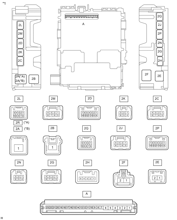
*A for LHD *B for RHD *1 Instrument Panel Junction Block Assembly - - 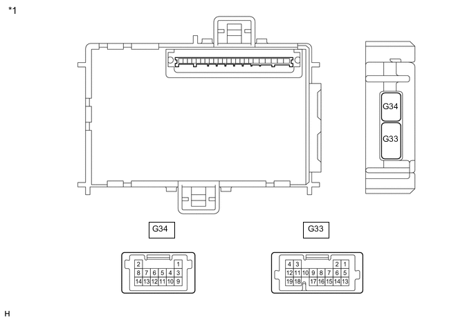
*1 Body ECU - -
-
Disconnect the G33 body ECU connector.
-
Remove the body ECU from the instrument panel junction block assembly.
-
for LHD:
-
for RHD:
-
-
Connect the instrument panel junction block assembly connectors.
-
Measure the resistance and voltage according to the value(s) in the table below.
Tech Tips
Measure the values on the wire harness side with the connector disconnected.
Terminal No.
(Symbol)
Wiring Color Terminal Description Condition Specified Condition A-6 (BECU) - Body ground - Battery power supply Always 11 to 14 V A-7 (IG) - Body ground - Ignition power supply (IG signal) Ignition switch ON → off 11 to 14 V → Below 1 V A-1 (GND) - Body ground - Ground Always Below 1 Ω A-18 (DCTY) - Body ground - Driver side door courtesy light switch input Driver side door closed (OFF) → open (ON) 10 kΩ or higher → Below 1 Ω G33-14 (PCTY) - Body ground LG - Body ground Front passenger side door courtesy light switch input Front passenger side door closed (OFF) → open (ON) 10 kΩ or higher → Below 1 Ω A-21 (ACTY) - Body ground - Door courtesy switch signal input except driver door All doors closed except driver door → any door open except driver door 10 kΩ or higher → Below 1 Ω A-20 (HCTY) - Body ground - Engine hood courtesy switch input Engine hood open (OFF) → closed (ON) 10 kΩ or higher → Below 1 Ω G33-8 (KSW) - Body ground* G - Body ground Unlock warning switch input Key not in key cylinder (OFF) → Key in key cylinder (ON) 10 kΩ or higher → Below 1 Ω
-
*: w/o Smart Entry and Start System
-
-
Connect the body ECU connectors.
-
for LHD:
-
for RHD:
-
-
Measure the voltage and check for pulses according to the value(s) in the table below.
Terminal No.
(Symbol)
Wiring Color Terminal Description Condition Specified Condition G33-15 (LSWD) - Body ground R - Body ground Driver side door unlock detection switch input Driver side door unlocked Below 1 V Driver side door unlock detection switch input Driver side door locked Pulse generation G33-17 (IND) - Body ground*1 Y - Body ground Security indicator light illumination Security indicator light illuminates
(It illuminates only for 27.5 seconds in alarm sounding state.)
3 to 10 V G33-6 (HAZ) - Body ground SB - Body ground Hazard warning signal output Theft deterrent system in alarm sounding state Pulse generation
(Below 1 V ← → 11 to 14 V)
2P-14 (SH) - Body ground*3 G - Body ground Security horn drive Security horn sounding
(Theft deterrent system in alarm sounding state)
Pulse generation
(Below 1 V ← → 11 to 14 V)
2D-14 (HORN) - Body ground GR - Body ground Vehicle horn drive Vehicle horns sounding
(Theft deterrent system in alarm sounding state)
Pulse generation
(Below 1 V ← → 11 to 14 V)
2N-3 (ACT-) - Body ground LA-W - Body ground*6
GR - Body ground*7
Door lock motor unlock drive output (all doors)*8
Door lock motor unlock drive output (except driver door)*9
Door control switch (power window regulator master switch assembly) or driver door key cylinder off Below 1 V Door control switch (power window regulator master switch assembly) or driver door key cylinder unlocked 11 to 14 V 2N-2 (ACT+) - Body ground LA-B - Body ground*6
LG - Body ground*7
Door lock motor lock drive output (all doors) Door control switch (power window regulator master switch assembly) or driver door key cylinder off Below 1 V Door control switch (power window regulator master switch assembly) or driver door key cylinder locked 11 to 14 V 2J-4 (ACTD) - Body ground*9 Y - Body ground Door lock motor unlock drive output (driver door) Door control switch (power window regulator master switch assembly) or driver door key cylinder off Below 1 V Door control switch (power window regulator master switch assembly) or driver door key cylinder unlocked 11 to 14 V G33-9 (PRG) - Body ground V - Body ground Signal output to door control receiver*1
Signal output to certification ECU (smart key ECU assembly)*2
Ignition switch off, all doors closed, 10 seconds elapsed after all doors locked and electrical key transmitter sub-assembly unlock switch not pressed 11 to 14 V Ignition switch off, all doors closed, 10 seconds elapsed after all doors locked and electrical key transmitter sub-assembly unlock switch pressed Pulse generation G33-16 (RDA) - Body ground W - Body ground Signal input from door control receiver*1
Signal input from certification ECU (smart key ECU assembly)*2
Ignition switch off, all doors closed, 10 seconds elapsed after all doors locked and electrical key transmitter sub-assembly unlock switch not pressed 11 to 14 V Ignition switch off, all doors closed, 10 seconds elapsed after all doors locked and electrical key transmitter sub-assembly unlock switch pressed Pulse generation G34-11 (SSCL) - Body ground*4 G - Body ground Theft warning siren drive Theft warning siren sounding (Theft deterrent system is in alarm sounding state) Pulse generation
(Below 1 V ← → 11 to 14 V)
G33-10 (SSW1) - Body ground*5 P - Body ground Intrusion sensor cancel switch signal Intrusion sensor cancel switch on Below 1 V Intrusion sensor cancel switch off Pulse generation G34-12 (ISIF) - Body ground*5 L - Body ground Intrusion sensor (theft warning ultrasonic sensor) signal input No moving object detected by sensor 11 to 14 V Moving object detected by sensor during arming preparation state or armed state Pulse generation G34-2 (GPBS) - Body ground*5 R - Body ground Glass breakage sensor signal Glass breakage sensor normal Below 2 V Glass breakage sensor malfunctioning 4.5 to 14 V
-
*1: w/o Smart Entry and Start System
-
*2: w/ Smart Entry and Start System
-
*3: w/ Security Horn Assembly
-
*4: w/ Theft Warning Siren
-
*5: w/ Intrusion Sensor
-
*6: w/o Door Control Battery
-
*7: w/ Door Control Battery
-
*8: w/o Double Locking
-
*9: w/ Double Locking
-
-
-
COMBINATION METER ASSEMBLY
-
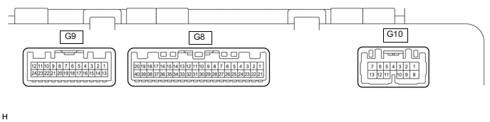
Measure the voltage, resistance and check for pulses according to the value(s) in the table below.
Terminal No. (Symbol) Wiring Color Terminal Description Condition Specified Condition G8-19 (+S) - Body ground V - Body ground Speed signal for other system (Output) Driving at approximately 20 km/h (12 mph) Pulse generation (See waveform) G9-12 (DOOR) - Body ground Y - Body ground Door courtesy switch signal except driver door All doors closed except driver door 11 to 14 V Any door open except driver door Below 1 V G9-15 (DCTY) - Body ground B - Body ground Driver side door condition signal Driver side door closed 11 to 14 V Driver side door open Below 1 V G9-16 (PCTY) - Body ground G - Body ground Front passenger side door condition signal Front passenger side door closed 11 to 14 V Front passenger side door open Below 1 V G9-17 (RLCY) - Body ground V - Body ground Rear door LH condition signal Rear door LH closed 11 to 14 V Rear door LH open Below 1 V G9-18 (RRCY) - Body ground LG - Body ground Rear door RH condition signal Rear door RH closed 11 to 14 V Rear door RH open Below 1 V G9-19 (BDCY) - Body ground B - Body ground Back door condition signal Back door closed 11 to 14 V Back door open Below 1 V G9-20 (GND) - Body ground* W-B - Body ground Ground Always Below 1 Ω G8-21 (B) - Body ground W - Body ground Battery Always 11 to 14 V *: w/ TFT Display
-
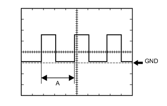
Using an oscilloscope, check waveform.
Waveform (Reference) Item Condition Tester Connection G8-19 (+S) - Body ground Tool setting 5 V/DIV, 20 ms./DIV Vehicle condition Driving at approximately 20 km/h (12 mph) Tech Tips
When the system is functioning normally, one wheel revolution generates 4 pulses. As the vehicle speed increases, the width indicated by (A) in the illustration narrows.
-
-