MAIN BODY ECU(for LHD) INSTALLATION
PROCEDURE
-
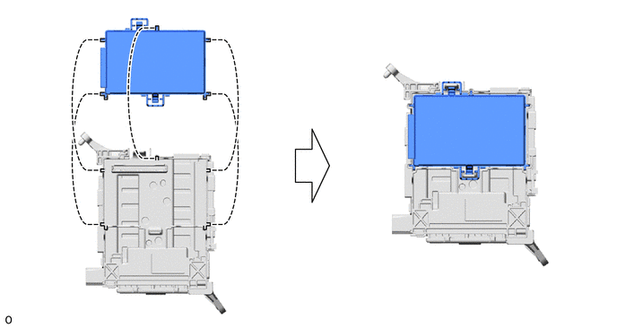
INSTALL BODY ECU
Note
-
Make sure that no foreign matter gets on the connecting surfaces.
-
Do not touch the body ECU connector and instrument panel junction block assembly connector.
-
If the body ECU has been replaced, it is necessary to initialize the body ECU.
-
Align the guide of the body ECU with the guide of the instrument panel junction block assembly and set the body ECU in place.
-
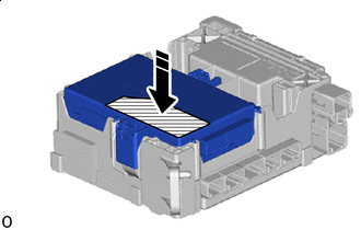

Push in this Direction 
Push Area Press the push area of the body ECU with the palm of one hand until the lock engages.
Note
-
Make sure to press only the push area.
-
Confirm the engagement of the body ECU and junction block by listening for the lock sound.
-
-
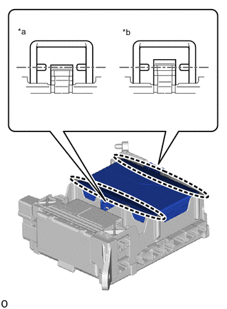
*a Correct *b Incorrect 
Check in this place Check that the body ECU rear surface and instrument panel junction block assembly enclosing wall are at the same height.
Tech Tips
When the lock is engaged correctly, the tip of the body ECU lock and body ECU lock engagement confirmation rib are in a straight line.
-
-
INSTALL WIRE HARNESS CLAMP BRACKET
-
Install the wire harness clamp bracket with the bolt.
- Torque:
- 12.5 N*m { 127 kgf*cm, 9 ft.*lbf }
-
-
INSTALL INSTRUMENT PANEL JUNCTION BLOCK ASSEMBLY
-
Connect the back side of the 8 connectors.
-
Install the instrument panel junction block assembly with the 2 nuts.
- Torque:
- 8.4 N*m { 86 kgf*cm, 74 in.*lbf }
-
Attach the 2 wire harness clamps.
-
Connect the front side of the 9 connectors.
-
-
INSTALL LOWER NO. 1 INSTRUMENT PANEL AIRBAG ASSEMBLY
-
INSTALL LOWER STEERING COLUMN COVER
-
INSTALL NO. 1 INSTRUMENT PANEL UNDER COVER SUB-ASSEMBLY
-
INSTALL NO. 2 INSTRUMENT PANEL GARNISH SUB-ASSEMBLY
-
INSTALL INSTRUMENT PANEL REGISTER BEZEL GARNISH
-
CONNECT CABLE TO NEGATIVE BATTERY TERMINAL
Note
When disconnecting the cable, some systems need to be initialized after the cable is reconnected.
-
PERFORM DIAGNOSTIC SYSTEM CHECK
for Type A:
for Type B:
-
CHECK SRS WARNING LIGHT
for Type A:
for Type B: