RADIO ANTENNA CORD INSTALLATION
PROCEDURE
-
INSTALL NO. 3 ANTENNA CORD SUB-ASSEMBLY
-
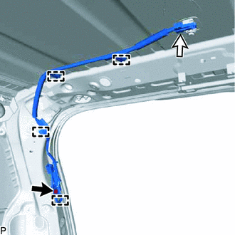
Attach the clamps and guide to install the No. 3 antenna cord sub-assembly.
-
Install the bolt and connect the connector.
- Torque:
- 8.7 N*m { 89 kgf*cm, 77 in.*lbf }
-
-
INSTALL NO. 2 ANTENNA CORD SUB-ASSEMBLY
-
Align the positioning tape of the No. 2 antenna cord sub-assembly with the protrusions of the roof headlining and wrap the positioning tape around them to install the positioning tape as shown in the illustration.
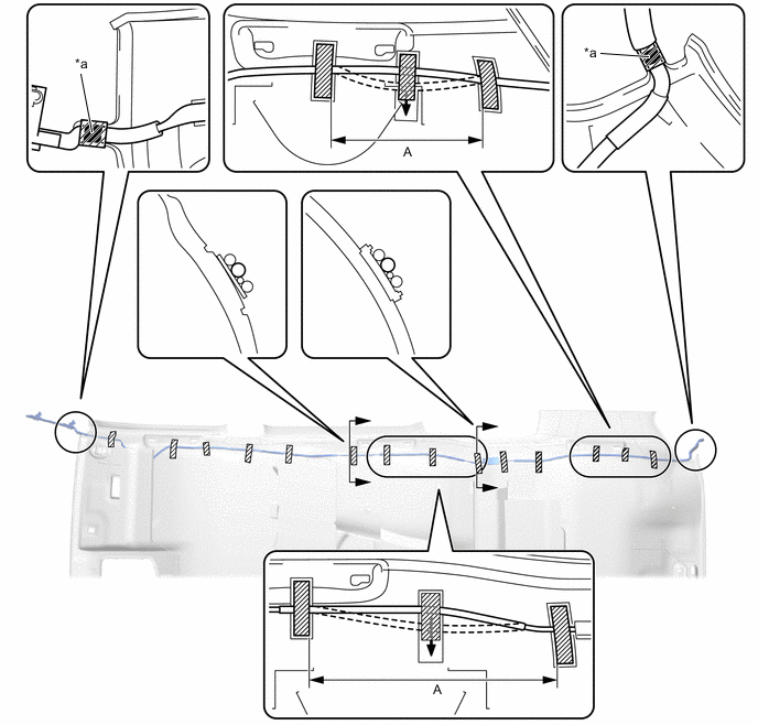
*a Positioning Tape - - 
Tape - - -
Install the No. 2 antenna cord sub-assembly with the tape aligned to each marking of the roof headlining assembly as shown in the illustration.
Tech Tips
-
Secure the surplus of the No. 2 antenna cord sub-assembly at the <A> area of the illustration.
-
Secure the front part of the No. 2 antenna cord sub-assembly aligning the edge of the positioning tape and tab section of the roof headlining assembly.
-
Secure the rear part of the No. 2 antenna cord sub-assembly aligning the edge of the positioning tape and tab section of the roof headlining assembly.
-
-
-
INSTALL ROOF HEADLINING ASSEMBLY
-
INSTALL ANTENNA CORD SUB-ASSEMBLY
-
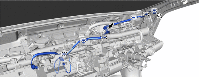
w/ Navigation System:
-
Install the antenna cord sub-assembly with the bolt.
- Torque:
- 8.4 N*m { 86 kgf*cm, 74 in.*lbf }
-
Attach the clamps shown in the illustration.
-
Connect the connector.
-
-
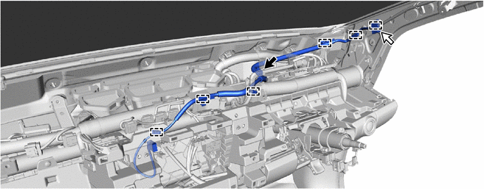
w/o Navigation System:
-
Install the antenna cord sub-assembly with the bolt.
- Torque:
- 8.4 N*m { 86 kgf*cm, 74 in.*lbf }
-
Attach the clamps shown in the illustration.
-
Connect the connector.
-
-
-
INSTALL UPPER INSTRUMENT PANEL SUB-ASSEMBLY
-
CONNECT CABLE TO NEGATIVE BATTERY TERMINAL
Note
When disconnecting the cable, some systems need to be initialized after the cable is reconnected Click here.
-
CHECK SRS WARNING LIGHT