REAR DIFFERENTIAL CARRIER ASSEMBLY(w/ Differential Lock) REASSEMBLY

CAUTION / NOTICE / HINT
Tech Tips
The following procedures are for BD22 (w/ Differential Lock).
PROCEDURE
-
INSTALL DIFFERENTIAL LOCK CAM RING
-
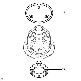
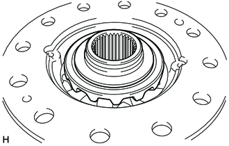
*1 Differential Lock Position Plate *2 Differential Lock Cam Ring Install the differential lock cam ring and differential lock position plate to the differential case RH.
-
-
INSTALL DIFFERENTIAL LOCK POSITION PLATE
-
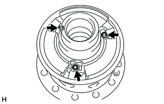
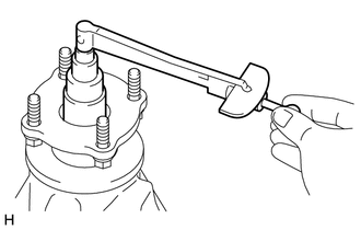
Using a T25 ''TORX'' socket wrench, install the 3 new screws.
- Torque:
- 6.9 N*m { 70 kgf*cm, 61 in.*lbf }
-
-
ASSEMBLE REAR DIFFERENTIAL CASE SUB-ASSEMBLY
-
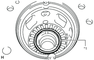
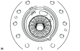
*1 Differential Lock Spring Install the differential lock spring to the differential case RH.
-
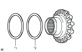
*1 Rear No. 2 Differential Side Gear Thrust Washer *2 Rear No. 3 Differential Side Gear Thrust Washer Install the rear No. 2 differential side gear thrust washer and rear No. 3 differential side gear thrust washer to the differential side gear (dog clutch).
-
Install the differential side gear (dog clutch) to the differential case RH.
-
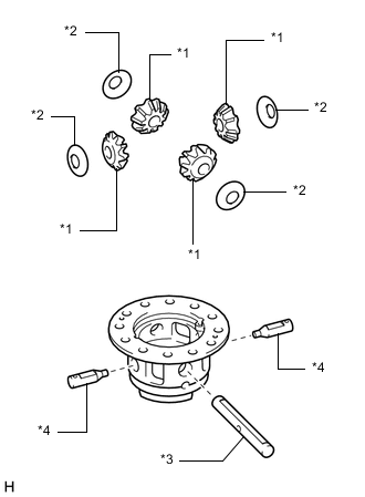
*1 Differential Pinion *2 Rear Differential Pinion Thrust Washer *3 Rear Differential Pinion Shaft *4 Rear No. 2 Differential Pinion Shaft Install the 4 differential pinions, 4 rear differential pinion thrust washers, rear differential pinion shaft and the 2 rear No. 2 differential pinion shafts in the differential case RH.
-
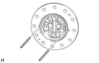
Install the 2 rear differential pinion shaft pins.
-
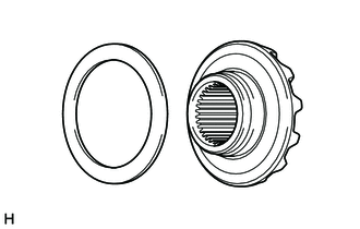
Install the rear No. 1 differential side gear thrust washer to the differential side gear.
-
Install the differential side gear.
-
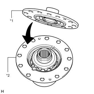
*1 Differential Case LH *2 Differential Case RH Install the differential case LH to the differential case RH.
-
Install the 2 screws.
- Torque:
- 4.5 N*m { 46 kgf*cm, 40 in.*lbf }
-
Measure the side gear backlash.
-
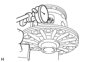
Using a dial indicator, measure the side gear backlash while holding one pinion gear toward the differential case.
Standard backlash 0.05 to 0.20 mm (0.00197 to 0.00787 in.) If the backlash is not as specified, install 2 side gear thrust washers with different thicknesses.
Tech Tips
Using the table below, select 3 thrust washers which will ensure that the backlash is within the specifications.
Standard Washer Thickness Item Thrust Washer Thickness mm (in.) Differential side gear No. 1 differential side gear thrust washer 1.05 to 1.15 (0.0414 to 0.0452) 1.15 to 1.25 (0.0453 to 0.0492) 1.25 to 1.35 (0.0493 to 0.0531) 1.35 to 1.45 (0.0532 to 0.0570) Differential side gear (dog clutch) No. 2 differential side gear thrust washer 1.05 to 1.15 (0.0414 to 0.0452) 1.15 to 1.25 (0.0453 to 0.0492) 1.25 to 1.35 (0.0493 to 0.0531) 1.35 to 1.45 (0.0532 to 0.0570) No. 3 differential side gear thrust washer 1.35 to 1.45 (0.0532 to 0.0570)
-
-
-
INSTALL DIFFERENTIAL RING GEAR
-
Clean the contact surfaces of the rear differential case sub-assembly and differential ring gear.
-
Heat the differential ring gear in boiling water that is approximately 100°C (212°F).
-
Carefully remove the differential ring gear from the boiling water.
-
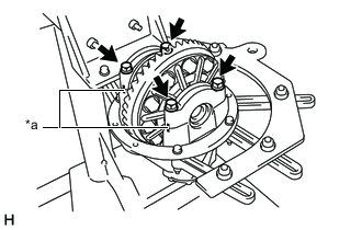
*a Matchmark After the moisture on the differential ring gear has completely evaporated, quickly align the matchmarks on the differential ring gear and electronic differential lock case and install the differential ring gear to the electronic differential lock case.
-
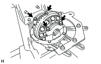
After the ring gear cools down sufficiently, apply adhesive to the 12 bolts and Temporarily install them.
Thread lock Toyota Genuine Adhesive 1360K, Three Bond1360K or equivalent -
Diametrically tighten the 12 bolts uniformly in several passes.
- Torque:
- 137 N*m { 1397 kgf*cm, 101 ft.*lbf }
-
-
INSTALL DIFFERENTIAL LOCK PLUNGER
-
Install the differential lock plunger to the rear differential case sub-assembly.
-
-
INSTALL DIFFERENTIAL LOCK COIL
-
Install the differential lock coil to the electronic differential lock case sub-assembly.
-
-
INSTALL DIFFERENTIAL SOLENOID WASHER
-
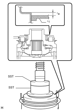
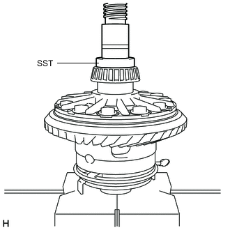
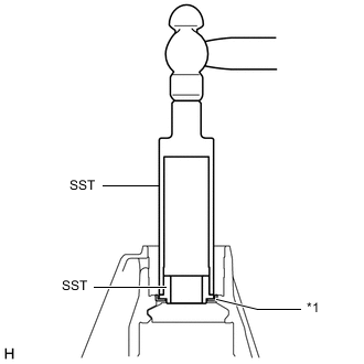
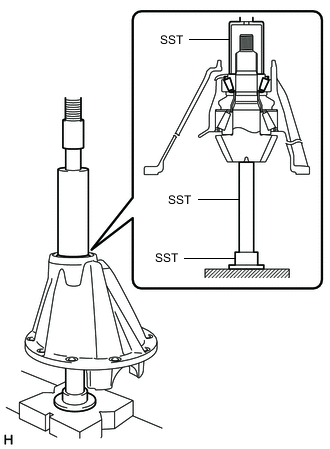
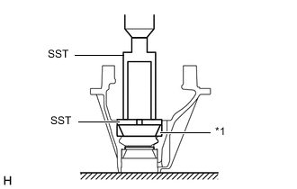
*1 Differential Solenoid Washer *a 0 to 0.15 mm Using SST and a press, press the differential solenoid washer to the electronic differential lock case sub-assembly.
- SST
- 09316-20011
- 09950-60010 ( 09951-00640 )
Differential solenoid washer depth 0 to 0.15 mm (0 to 0.00590 in.) Note
Make sure that the end face of the differential solenoid washer does not protrude from the end face of the electronic differential lock case sub-assembly.
-
-
INSTALL REAR DIFFERENTIAL CASE BEARING
-
for LH Side (Ring Gear Side):
-
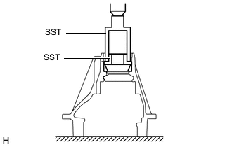
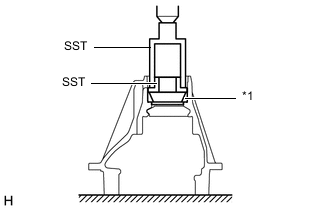
Using SST and a press, press a new rear differential case bearing (inner) to the electronic differential lock case sub-assembly.
- SST
- 09950-60010 ( 09951-00600 )
-
-
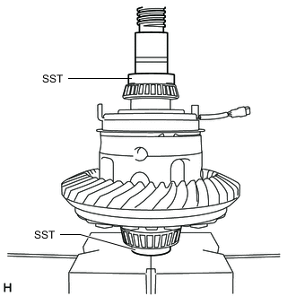
for RH Side (Differential Lock Coil Side):
-
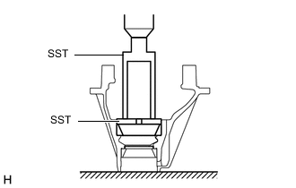
Using SST and a press, press a new rear differential case bearing (inner) to the electronic differential lock case sub-assembly.
- SST
- 09950-60010 ( 09951-00480, 09951-00570 )
-
-
-
INSPECT DIFFERENTIAL RING GEAR RUNOUT
-
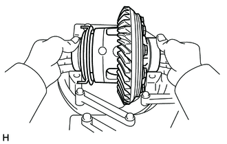
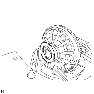
Install the differential case on the carrier, and install the 2 plate washers so that there is no play in the bearing.
-
Install the 2 bearing caps with the 4 bolts.
- Torque:
- 113 N*m { 1152 kgf*cm, 83 ft.*lbf }
-
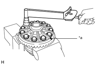
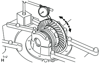
*a 98 mm (3.86 in.) Using a dial indicator, measure the runout of the differential ring gear.
Maximum runout 0.07 mm (0.00276 in.) -
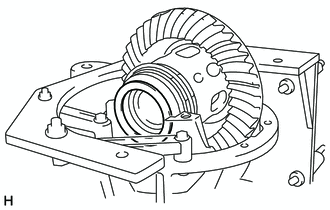
Remove the 2 differential bearing caps, 2 plate washers and electronic differential lock case sub-assembly.
-
-
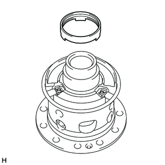
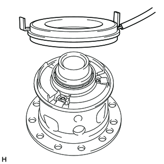
INSTALL DIFFERENTIAL OIL STORAGE RING
-
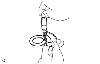
*1 Differential Oil Storage Ring Using SST and a hammer, tap in the differential oil storage ring.
- SST
- 09316-60011 ( 09316-00011, 09316-00071 )
Note
Be careful not to damage the differential oil storage ring.
-
-
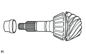
INSTALL REAR DRIVE PINION FRONT TAPERED ROLLER BEARING
-
Using SST and a press, press the rear drive pinion front tapered roller bearing (outer) into the differential carrier.
- SST
- 09316-60011 ( 09316-00011, 09316-00031 )
-
-
INSTALL REAR DRIVE PINION REAR TAPERED ROLLER BEARING
-
Using SST and a press, press the adjust shim and rear drive pinion rear tapered roller bearing (outer) into the differential carrier.
- SST
- 09316-60011 ( 09316-00011 )
- 09951-01000
Tech Tips
First, install an adjust shim that has the same thickness as the removed adjust shim. After checking the tooth contact pattern, replace the adjust shim with one of a different thickness if necessary.
-
-
INSTALL REAR DRIVE PINION REAR TAPERED ROLLER BEARING
-
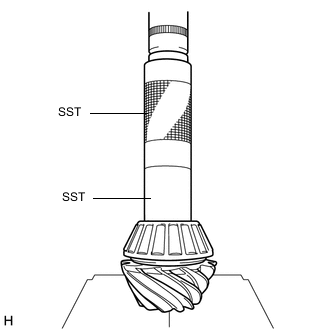
Using SST and a press, press the rear drive pinion rear tapered roller bearing (inner) onto the differential drive pinion.
- SST
- 09309-37010
- 09630-24014 ( 09620-24051 )
-
-
ADJUST DIFFERENTIAL DRIVE PINION PRELOAD
-
Install the differential drive pinion, rear drive pinion tapered roller bearing (inner).
- SST
- 09316-60011 ( 09316-00011, 09316-00041 )
- 09608-04031
Tech Tips
Install the spacer and oil seal after adjusting the gear contact pattern.
-
Install the rear differential drive pinion oil slinger.
-
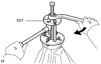
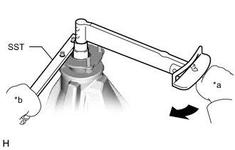
*a Turn *b Hold Using SST, install the rear drive pinion companion flange sub-assembly with dust deflector.
- SST
- 09950-30012 ( 09951-03010, 09953-03010, 09954-03010, 09955-03030, 09956-03040 )
Note
Before using SST (center bolt), apply hypoid gear oil to its threads and tip.
-
Adjust the drive pinion preload by tightening the rear drive pinion nut.
-
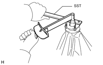
Using SST to hold the rear drive pinion companion flange sub-assembly with dust deflector in place, slowly tighten the rear drive pinion nut within the drive pinion preload adjustment range so that it reaches the specified drive pinion preload (at Starting).
- SST
- 09330-00021 ( 09330-00030 )
Limit torque value 457 N*m (4660 kgf*cm, 337 ft.*lbf) or less Note
-
As there is no spacer, tighten a little at a time. Be careful not to overtighten the nut.
-
Apply hypoid gear oil LSD to the drive pinion thread and nut seat face.
-
Using a torque wrench, measure the preload.
Standard Drive Pinion Preload (Starting Torque) Bearing Preload New bearing 1.51 to 3.48 N*m (16 to 35 kgf*cm, 14 to 30 in.*lbf) Reused bearing 1.53 to 3.34 N*m (16 to 34 kgf*cm, 14 to 29 in.*lbf) Note
-
For a more accurate measurement, rotate the bearing forward and backward several times before measuring.
-
Record the differential drive pinion preload for the total preload measurement.
-
-
-
INSTALL ELECTRONIC DIFFERENTIAL LOCK CASE SUB-ASSEMBLY
-
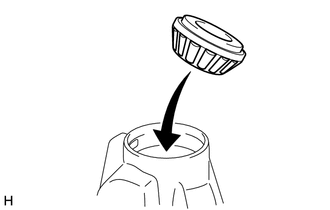
Place the 2 rear differential case bearings (outer) to their respective bearings.
Tech Tips
Make sure the right and left races are not interchanged.
-
-
ADJUST DIFFERENTIAL RING GEAR BACKLASH
-
Install the plate washer to the RH side (differential lock coil side).
Note
Make sure that the differential ring gear has backlash.
-
Using a dial indicator, while holding the rear drive pinion companion flange sub-assembly with dust deflector, measure the ring gear backlash.
Standard backlash (reference) 0.10 to 0.20 mm (0.00394 to 0.00787 in.) -
Refer to the backlash when selecting a plate washer for the RH side (differential lock coil side).
-
Select a plate washer for the LH side (ring gear side) so that there is no gap between the rear differential case bearing (outer) and differential case.
-
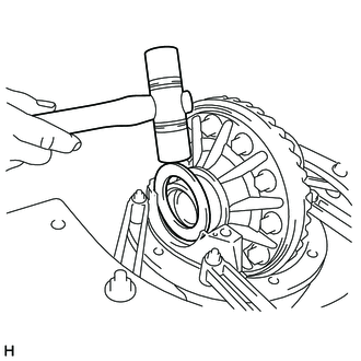
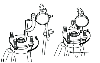
Using a plastic-faced hammer, install the plate washer to the LH side (ring gear side).
-
Using a dial indicator, adjust the ring gear backlash until it is within the specification.
Standard backlash 0.10 to 0.20 mm (0.00394 to 0.00787 in.) Tech Tips
If the backlash is not within the specification, adjust it by either increasing or decreasing the thickness of the plate washers on both sides by an equal amount.
Note
-
There should be no clearance between the plate washer and case.
-
Make sure that there is ring gear backlash.
-
-
-
ADJUST SIDE BEARING PRELOAD
-
After adjusting the backlash of the differential ring gear, remove the plate washer from the LH side (ring gear side).
-
Using a micrometer, measure the thickness of the plate washer.
-
Using the backlash as a reference, select a new plate washer that is 0.05 to 0.20 mm (0.00197 to 0.00787 in.) thicker than the removed plate washer and, using a plastic-faced hammer, tap it in so that it fits against the bearing.
Tech Tips
Select a plate washer which can be pressed in 2/3 of the full amount with your finger.
-
Recheck the ring gear backlash.
Standard backlash 0.10 to 0.20 mm (0.00394 to 0.00787 in.) If the backlash is not within the specification, adjust it by either increasing or decreasing the thickness of the washers on both sides by an equal amount.
Tech Tips
An approximately 0.02 mm (0.000787 in.) change in each plate washer results in a 0.03 mm (0.00118 in.) change in the backlash.
Standard Washer LH (Ring Gear Side) Part No. Thickness mm (in.) Part No. Thickness mm (in.) 90564-59044 2.07 to 2.09 (0.0815 to 0.0822) 90564-59060 2.39 to 2.41 (0.0941 to 0.0948) 90564-59045 2.09 to 2.11 (0.0823 to 0.0830) 90564-59061 2.41 to 2.43 (0.0949 to 0.0956) 90564-59046 2.11 to 2.13 (0.0831 to 0.0838) 90564-59062 2.43 to 2.45 (0.0957 to 0.0964) 90564-59047 2.13 to 2.15 (0.0839 to 0.0846) 90564-59063 2.45 to 2.47 (0.0965 to 0.0972) 90564-59048 2.15 to 2.17 (0.0847 to 0.0854) 90564-59064 2.47 to 2.49 (0.0973 to 0.0980) 90564-59049 2.17 to 2.19 (0.0855 to 0.0862) 90564-59065 2.49 to 2.51 (0.0981 to 0.0988) 90564-59050 2.19 to 2.21 (0.0863 to 0.0870) 90564-59066 2.51 to 2.53 (0.0989 to 0.0996) 90564-59051 2.21 to 2.23 (0.0871 to 0.0877) 90564-59067 2.53 to 2.55 (0.0997 to 0.1003) 90564-59052 2.23 to 2.25 (0.0878 to 0.0885) 90564-59068 2.55 to 2.57 (0.1004 to 0.1011) 90564-59053 2.25 to 2.27 (0.0886 to 0.0893) 90564-59069 2.57 to 2.59 (0.1012 to 0.1019) 90564-59054 2.27 to 2.29 (0.0894 to 0.0901) 90564-59070 2.59 to 2.61 (0.1020 to 0.1027) 90564-59055 2.29 to 2.31 (0.0902 to 0.0909) 90564-59071 2.61 to 2.63 (0.1028 to 0.1035) 90564-59056 2.31 to 2.33 (0.0910 to 0.0917) 90564-59072 2.63 to 2.65 (0.1036 to 0.1043) 90564-59057 2.33 to 2.35 (0.0918 to 0.0925) 90564-59073 2.65 to 2.67 (0.1044 to 0.1051) 90564-59058 2.35 to 2.37 (0.0926 to 0.0933) 90564-59074 2.67 to 2.69 (0.1052 to 0.1059) 90564-59059 2.37 to 2.39 (0.0934 to 0.0940) - - Standard Washer RH (Differential Lock Coil Side) Part No. Thickness mm (in.) Part No. Thickness mm (in.) 90564-59075 2.05 to 2.07 (0.0807 to 0.0814) 90564-59091 2.37 to 2.39 (0.0934 to 0.0940) 90564-59076 2.07 to 2.09 (0.0815 to 0.0822) 90564-59092 2.39 to 2.41 (0.0941 to 0.0948) 90564-59077 2.09 to 2.11 (0.0823 to 0.0830) 90564-59093 2.41 to 2.43 (0.0949 to 0.0956) 90564-59078 2.11 to 2.13 (0.0831 to 0.0838) 90564-59094 2.43 to 2.45 (0.0957 to 0.0964) 90564-59079 2.13 to 2.15 (0.0839 to 0.0846) 90564-59095 2.45 to 2.47 (0.0965 to 0.0972) 90564-59080 2.15 to 2.17 (0.0847 to 0.0854) 90564-59096 2.47 to 2.49 (0.0973 to 0.0980) 90564-59081 2.17 to 2.19 (0.0855 to 0.0862) 90564-59097 2.49 to 2.51 (0.0981 to 0.0988) 90564-59082 2.19 to 2.21 (0.0863 to 0.0870) 90564-59098 2.51 to 2.53 (0.0989 to 0.0996) 90564-59083 2.21 to 2.23 (0.0871 to 0.0877) 90564-59099 2.53 to 2.55 (0.0997 to 0.1003) 90564-59084 2.23 to 2.25 (0.0878 to 0.0885) 90564-59100 2.55 to 2.57 (0.1004 to 0.1011) 90564-59085 2.25 to 2.27 (0.0886 to 0.0893) 90564-59101 2.57 to 2.59 (0.1012 to 0.1019) 90564-59086 2.27 to 2.29 (0.0894 to 0.0901) 90564-59102 2.59 to 2.61 (0.1020 to 0.1027) 90564-59087 2.29 to 2.31 (0.0902 to 0.0909) 90564-59103 2.61 to 2.63 (0.1028 to 0.1035) 90564-59088 2.31 to 2.33 (0.0910 to 0.0917) 90564-59104 2.63 to 2.65 (0.1036 to 0.1043) 90564-59089 2.33 to 2.35 (0.0918 to 0.0925) 90564-59105 2.65 to 2.67 (0.1044 to 0.1051) 90564-59090 2.35 to 2.37 (0.0926 to 0.0933) 90564-59106 2.67 to 2.69 (0.1052 to 0.1059)
-
-
INSPECT TOTAL PRELOAD
-
Using a torque wrench, measure the preload with the teeth of the differential drive pinion and differential ring gear in contact.
Standard Total Preload Reduction Ratio Item Specified Condition 3.583 New bearing 1.8 to 4.1 N*m (19 to 41 kgf*cm, 16 to 36 in.*lbf) Reused bearing 1.82 to 3.92 N*m (19 to 39 kgf*cm, 17 to 34 in.*lbf) 3.909 New bearing 1.77 to 4.05 N*m (19 to 41 kgf*cm, 16 to 35 in.*lbf) Reused bearing 1.8 to 3.87 N*m (19 to 39 kgf*cm, 16 to 34 in.*lbf) 4.100 New bearing 1.76 to 4.02 N*m (18 to 40 kgf*cm, 16 to 35 in.*lbf) Reused bearing 1.79 to 3.84 N*m (19 to 39 kgf*cm, 16 to 33 in.*lbf) 4.555 New bearing 1.74 to 3.97 N*m (18 to 40 kgf*cm, 16 to 35 in.*lbf) Reused bearing 1.76 to 3.79 N*m (18 to 38 kgf*cm, 16 to 33 in.*lbf) If necessary, disassemble and inspect the differential.
-
-
INSPECT TOOTH CONTACT BETWEEN RING GEAR AND DRIVE PINION
-
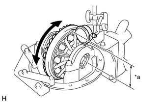
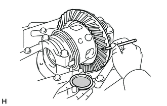
Coat 3 or 4 teeth at 3 different positions on the differential ring gear with Prussian blue.
-
Hold the companion flange firmly in place and rotate the differential ring gear in both directions.
-
Inspect the tooth contact pattern.
-
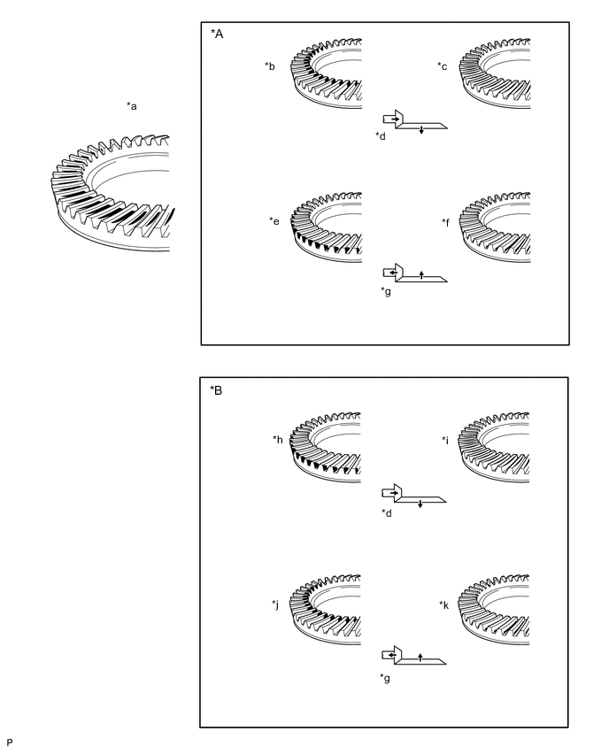
*A Drive Side *B Coast Side *a Proper Contact *b Toe Contact *c Face Contact *d Select an adjusting washer that will shift the drive pinion closer to the ring gear. *e Heel Contact *f Flank Contact *g Select an adjusting washer that will shift the drive pinion away from the ring gear. *h Heel Contact *i Flank Contact *j Toe Contact *k Face Contact - - -
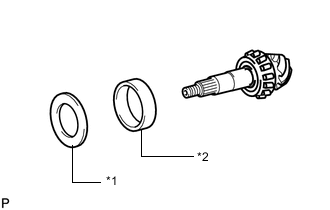
*1 Adjust Shim *2 Rear Drive Pinion Rear Tapered Roller Bearing (Outer) If the teeth are not contacting properly, use the following chart to select a adjust shim.
Standard Adjust Shim Thickness Part No. Thickness mm (in.) Part No. Thickness mm (in.) 90564-78001 1.71 to 1.73 (0.0674 to 0.0681) 90564-78013 1.95 to 1.97 (0.0768 to 0.0775) 90564-78002 1.73 to 1.75 (0.0682 to 0.0688) 90564-78014 1.97 to 1.99 (0.0776 to 0.0783) 90564-78003 1.75 to 1.77 (0.0689 to 0.0696) 90564-78015 1.99 to 2.01 (0.0784 to 0.0791) 90564-78004 1.77 to 1.79 (0.0697 to 0.0704) 90564-78016 2.01 to 2.03 (0.0792 to 0.0799) 90564-78005 1.79 to 1.81 (0.0705 to 0.0712) 90564-78017 2.03 to 2.05 (0.0780 to 0.0807) 90564-78006 1.81 to 1.83 (0.0713 to 0.0720) 90564-78018 2.05 to 2.07 (0.0808 to 0.0814) 90564-78007 1.83 to 1.85 (0.0721 to 0.0728) 90564-78019 2.07 to 2.09 (0.0815 to 0.0822) 90564-78008 1.85 to 1.87 (0.0729 to 0.0736) 90564-78020 2.09 to 2.11 (0.0823 to 0.0830) 90564-78009 1.87 to 1.89 (0.0737 to 0.0744) 90564-78021 2.11 to 2.13 (0.0831 to 0.0838) 90564-78010 1.89 to 1.91 (0.0745 to 0.0751) 90564-78022 2.13 to 2.15 (0.0839 to 0.0846) 90564-78011 1.91 to 1.93 (0.0752 to 0.0759) 90564-78023 2.15 to 2.17 (0.0847 to 0.0854) 90564-78012 1.93 to 1.95 (0.0760 to 0.0767) 90564-78024 2.17 to 2.19 (0.0855 to 0.0862) -
-
-
REMOVE REAR DRIVE PINION NUT
-
REMOVE REAR DRIVE PINION COMPANION FLANGE SUB-ASSEMBLY WITH DUST DEFLECTOR
-
REMOVE REAR DIFFERENTIAL DRIVE PINION OIL SLINGER
-
REMOVE DIFFERENTIAL BEARING CAP
-
REMOVE ELECTRONIC DIFFERENTIAL LOCK CASE SUB-ASSEMBLY
-
REMOVE DIFFERENTIAL DRIVE PINION
-
REMOVE REAR DRIVE PINION FRONT TAPERED ROLLER BEARING
-
REMOVE REAR DIFFERENTIAL DRIVE PINION BEARING SPACER
-
REMOVE REAR DRIVE PINION FRONT TAPERED ROLLER BEARING
-
REMOVE DIFFERENTIAL OIL STORAGE RING
-
REMOVE REAR DRIVE PINION REAR TAPERED ROLLER BEARING
-
INSTALL REAR DRIVE PINION REAR TAPERED ROLLER BEARING
-
*1 Rear Drive Pinion Rear Tapered Roller Bearing (Outer) Using SST and a press, press the adjust shim and rear drive pinion rear tapered roller bearing (outer) into the differential carrier.
- SST
- 09316-60011 ( 09316-00011 )
- 09951-01000
-
-
INSTALL DIFFERENTIAL OIL STORAGE RING
-
*1 Differential Oil Storage Ring Using SST and a hammer, tap in a new differential oil storage ring.
- SST
- 09316-60011 ( 09316-00011 )
Note
Be careful not to damage the differential oil storage ring.
-
-
INSTALL REAR DRIVE PINION FRONT TAPERED ROLLER BEARING
-
*1 Rear Drive Pinion Front Tapered Roller Bearing (Outer) Using SST and a press, press the rear drive pinion front tapered roller bearing (outer) into the differential carrier.
- SST
- 09316-60011 ( 09316-00011, 09316-00031 )
-
-
INSTALL REAR DIFFERENTIAL DRIVE PINION BEARING SPACER
-
Install a new rear differential drive pinion bearing spacer.
-
-
INSTALL REAR DRIVE PINION FRONT TAPERED ROLLER BEARING
-
Install the rear drive pinion front tapered roller bearing (inner) to the drive pinion.
-
-
INSTALL DIFFERENTIAL DRIVE PINION
-
Using SST and a press, install the differential drive pinion.
- SST
- 09316-60011 ( 09316-00011, 09316-00041 )
- 09608-04031
-
-
INSTALL NO. 1 TRANSFER INDICATOR SWITCH (REAR DIFFERENTIAL LOCK POSITION SWITCH)
-
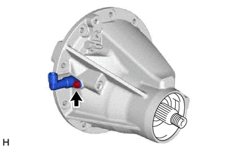
Install a new No. 1 transfer indicator switch (rear differential lock position switch) with the bolt.
- Torque:
- 9.0 N*m { 92 kgf*cm, 80 in.*lbf }
-
-
INSTALL ELECTRONIC DIFFERENTIAL LOCK CASE SUB-ASSEMBLY
-
Place the 2 new bearing outer races to their respective bearings.
-
-
INSTALL WIRING HARNESS CONNECTOR
-
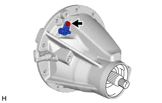
Install a new wiring harness connector with the bolt.
- Torque:
- 9.0 N*m { 92 kgf*cm, 80 in.*lbf }
-
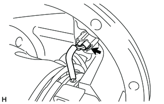
Connect the connector.
-
-
INSTALL DIFFERENTIAL BEARING CAP
-
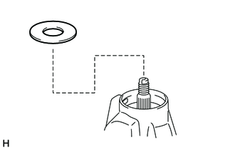
Install the 2 plate washers.
-
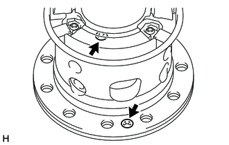
*a Matchmark Align the matchmarks on the differential bearing cap and differential carrier.
-
Install the right and left differential bearing caps with the 4 bolts.
- Torque:
- 113 N*m { 1152 kgf*cm, 83 ft.*lbf }
-
-
INSTALL REAR DIFFERENTIAL DRIVE PINION OIL SLINGER
-
Install the rear differential drive pinion oil slinger to the differential drive pinion.
-
-
INSTALL REAR DIFFERENTIAL CARRIER OIL SEAL
-
INSTALL REAR DRIVE PINION COMPANION FLANGE SUB-ASSEMBLY WITH DUST DEFLECTOR
-
*a Turn *b Hold Using SST, install the rear drive pinion companion flange sub-assembly with dust deflector.
- SST
- 09950-30012 ( 09951-03010, 09953-03010, 09954-03010, 09955-03030, 09956-03040 )
Note
Before using SST (center bolt), apply hypoid gear oil to its threads and tip.
-
Apply hypoid gear oil LSD to the drive pinion thread and nut seat face.
-
*a Turn *b Hold Using SST to hold the companion flange in place, install a new nut.
- SST
- 09330-00021 ( 09330-00030 )
Limit torque value 457 N*m (4660 kgf*cm, 337 ft.*lbf) or less
-
-
INSPECT TOTAL PRELOAD
-
Using a torque wrench, measure the preload with the teeth of the differential drive pinion and differential ring gear in contact.
-
Using a torque wrench, measure the total preload.
Standard Total Preload Reduction Ratio Bearing Preload 3.583 New bearing 1.9 to 4.2 N*m (20 to 42 kgf*cm, 17 to 37 in.*lbf) Reused bearing 1.92 to 4.02 N*m (20 to 40 kgf*cm, 17 to 35 in.*lbf) 3.909 New bearing 1.87 to 4.15 N*m (20 to 42 kgf*cm, 17 to 36 in.*lbf) Reused bearing 1.9 to 3.97 N*m (20 to 40 kgf*cm, 17 to 35 in.*lbf) 4.100 New bearing 1.86 to 4.12 N*m (19 to 42 kgf*cm, 17 to 36 in.*lbf) Reused bearing 1.89 to 3.94 N*m (20 to 40 kgf*cm, 17 to 34 in.*lbf) 4.555 New bearing 1.84 to 4.07 N*m (19 to 41 kgf*cm, 17 to 36 in.*lbf) Reused bearing 1.86 to 3.89 N*m (19 to 39 kgf*cm, 17 to 34 in.*lbf) If necessary, disassemble and inspect the differential.
-
-
INSPECT DIFFERENTIAL RING GEAR BACKLASH
-
Using a dial indicator, check the backlash of the differential ring gear.
Standard backlash 0.10 to 0.20 mm (0.00394 to 0.00787 in.) If the backlash is not as specified, adjust the side bearing preload or perform repairs as necessary.
Tech Tips
Perform the measurement at 3 or more positions around the circumference of the differential ring gear.
-
-
INSPECT REAR DRIVE PINION COMPANION FLANGE SUB-ASSEMBLY
-
*a 30 mm (1.18 in.) Using a dial indicator, measure the runout of the companion flange vertically and laterally.
Maximum Runout Runout Maximum Vertical runout 0.10 mm (0.00394 in.) Lateral runout 0.10 mm (0.00394 in.)
-
-
STAKE DRIVE PINION NUT
-
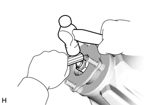
Using a chisel and hammer, stake the drive pinion nut.
-