STEERING KNUCKLE INSTALLATION

CAUTION / NOTICE / HINT
Tech Tips
-
Use the same procedure for the RH and LH sides.
-
The procedure listed below is for the LH side.
PROCEDURE
-
INSTALL STEERING KNUCKLE LH
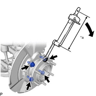
*a Torque Wrench Fulcrum Length
-
Apply MP grease to a new O-ring.
-
Install the O-ring to the front axle hub sub-assembly LH.
-
Install the dust cover and front axle hub sub-assembly LH to the steering knuckle LH with the 4 bolts.
- Torque:
- Specified tightening torque
- 80 N*m { 816 kgf*cm, 59 ft.*lbf }
Tech Tips
-
Calculate the torque wrench reading when changing the fulcrum length of the torque wrench.
-
When using a ball joint lock nut wrench (fulcrum length of 149 mm (5.866 in.)) + torque wrench (fulcrum length of 380 mm (14.961 in.)): 57.5 N*m (586 kgf*cm, 42 ft.*lbf).
-
-
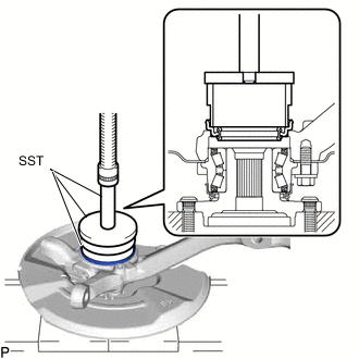
INSTALL FRONT AXLE HUB DUST SEAL
-
Using SST and a press, press in a new front axle hub dust seal.
- SST
- 09527-17011
- 09950-70010 ( 09951-07100 )
- 09951-01000
-
-
CONNECT FRONT UPPER SUSPENSION ARM ASSEMBLY LH
-
Install the front upper suspension arm assembly LH to the steering knuckle LH with a nut.
- Torque:
- 110 N*m { 1122 kgf*cm, 81 ft.*lbf }
-
Install a new clip.
Note
If the holes for the clip are not aligned, tighten the nut an additional 60°.
-
-
CONNECT FRONT LOWER NO. 1 SUSPENSION ARM ASSEMBLY LH
-
Connect the front lower No. 1 suspension arm assembly LH to the steering knuckle LH with the 2 bolts.
- Torque:
- 160 N*m { 1632 kgf*cm, 118 ft.*lbf }
-
-
CONNECT TIE ROD END SUB-ASSEMBLY LH
-
CONNECT FRONT STABILIZER LINK ASSEMBLY LH
-
Connect the front stabilizer link assembly LH to the steering knuckle LH with the nut.
- Torque:
- 94 N*m { 959 kgf*cm, 69 ft.*lbf }
Tech Tips
If the ball joint turns together with the nut, use a 6 mm hexagon wrench to hold the stud.
-
-
INSTALL FRONT AXLE SHAFT NUT LH
-
INSTALL FRONT AXLE HUB GREASE CAP
-
INSTALL FRONT DISC
-
INSTALL FRONT DISC BRAKE CYLINDER ASSEMBLY LH
-
CONNECT FRONT SPEED SENSOR LH
-
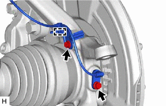
Install the skid control sensor clamp to the steering knuckle with the bolt.
- Torque:
- 13.5 N*m { 138 kgf*cm, 10 ft.*lbf }
-
Install the speed sensor to the steering knuckle with the bolt.
- Torque:
- 8.5 N*m { 87 kgf*cm, 75 in.*lbf }
Note
-
Make sure there are no pieces of iron or other foreign matter attached to the sensor tip.
-
While inserting the speed sensor into the knuckle hole, do not strike or damage the sensor tip.
-
After installing the speed sensor, make sure there is no clearance or foreign matter between the sensor stay part and the knuckle.
-
When installing the sensor, do not twist the wire harness.
-
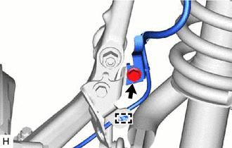
Install the harness clamp with the bolt.
- Torque:
- 32 N*m { 326 kgf*cm, 24 ft.*lbf }
Note
-
When installing the clamp, do not twist the wire harness.
-
Make sure the clamp rotation stopper touches the installation position.
-
Attach the clamp.
-
-
INSTALL FRONT WHEEL
-
INSPECT AND ADJUST FRONT WHEEL ALIGNMENT
-
CHECK ABS SPEED SENSOR SIGNAL
-
PERFORM INITIALIZATION (w/ Automatic Headlight Beam Level Control System)
-
INSPECT AUTOMATIC LIGHT CONTROL SYSTEM (w/ Automatic Headlight Beam Level Control System)
-
INSPECT HEADLIGHT AIMING (w/ Automatic Headlight Beam Level Control System)